PK-01Pocket music player
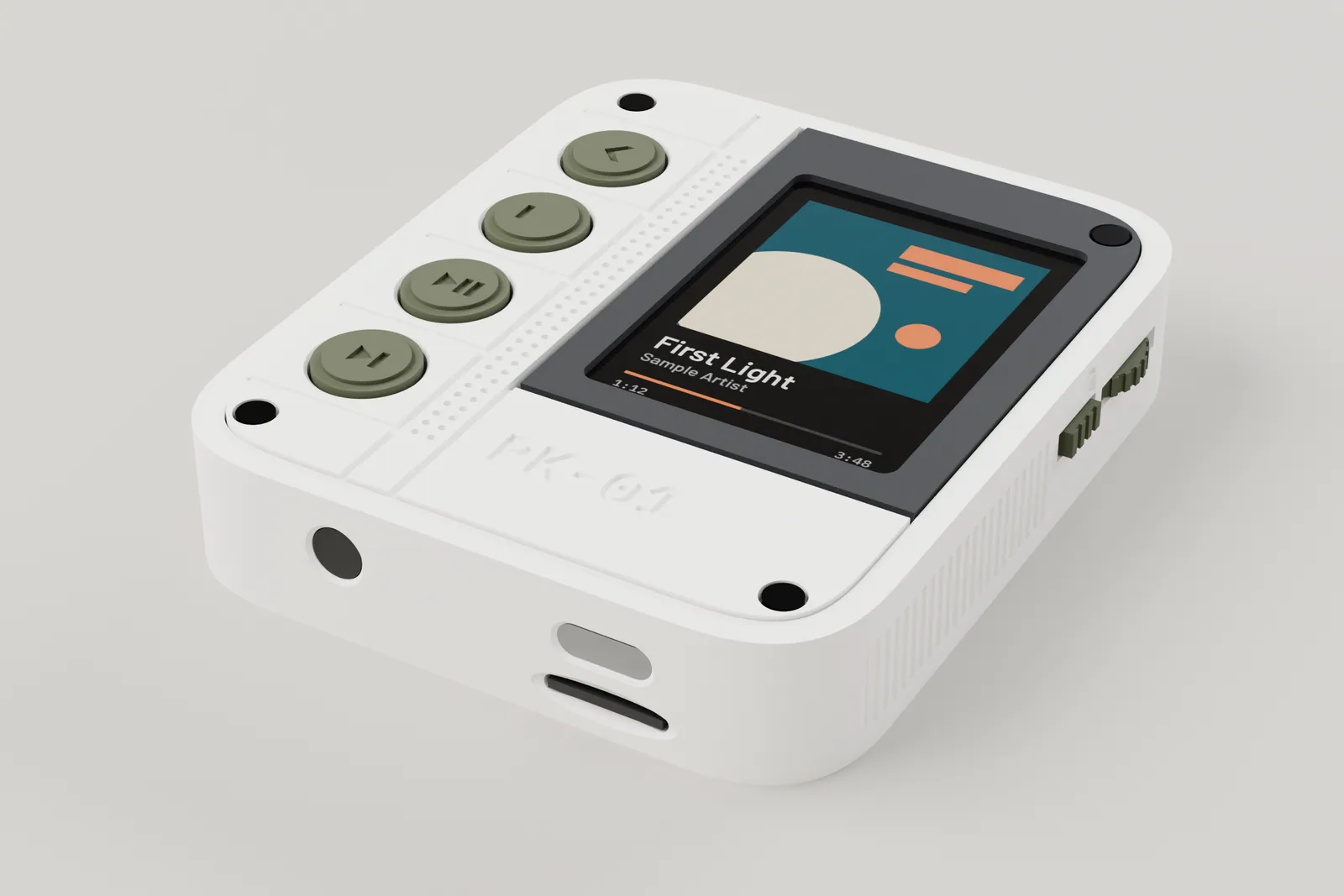
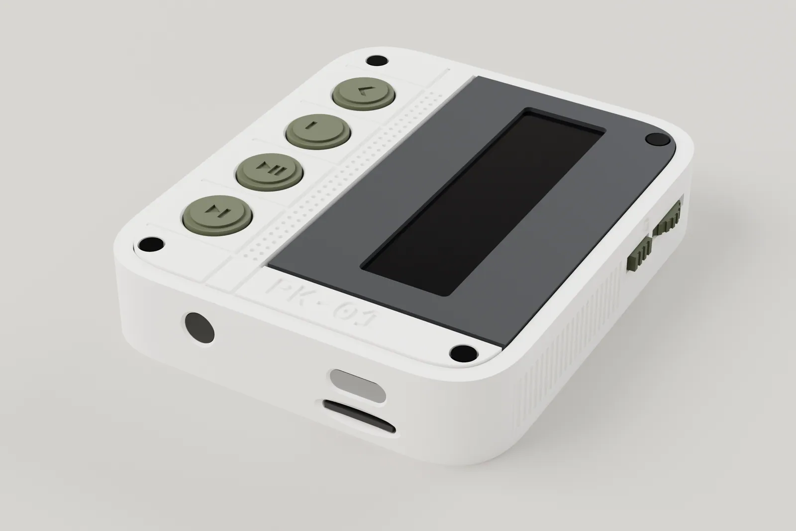
A pocket music player you build yourself, 66 by 78 millimetres and 15 thick. It plays FLAC and WAV up to 24 bit / 96 kHz through a 3.5 mm headphone jack, or over Bluetooth to wireless headphones and speakers. Everything inside is a bought module wired by hand: an Adafruit QT Py ESP32 Pico board, a screen module, a DAC board, a charger module and a LiPo cell. The case is printed in resin and painted. Your music library lives on a microSD card in a slot at the port end. Flat record cards, each carrying one album, slide into a slot in the top edge; that reader is optional.
This manual follows the CAD model as it stands. Every bought part is modelled at its nominal size from a datasheet or listing, and nothing has been built and measured yet. Measure each module when it arrives (section 04) before you print the parts that wrap it. The firmware in this tree is a draft that does not yet run on the QT Py (section 07).
- Size
- 66 x 7815.0 mm thick
- Plays
- FLAC, WAVup to 24 bit / 96 kHz
- Output
- Jack + Bluetoothheadphones and speakers
- Screen
- 2.0 inch240 x 320 colour
- Screen
- 1.9 inch170 x 320 colour
- Screen
- 1.69 inch240 x 280 colour
- Screen
- 1.47 inch172 x 320 colour
- Screen
- 2.08 inch OLED256 x 64 mono bar
- Screen
- 2.25 inch bar76 x 284 colour
- Library
- microSDin a slot at the port end
- Cards
- Record cardsflat, in the top edge (optional)
Choose your build
One body, three sets of choices. The shell, deck, keys, wheel, ports and the top edge slot are the same in every build. Pick a preset, or pick the screen, the card type and the parts tier yourself: the rest of this page then shows your build only.
Or choose each part yourself
Three choicesScreen
Sets the screen module you buy, the band you print and, for the two bars, the deck and a screen carrier. All six fit the one shell.Record cards
How the cards you make carry their music. Both sit in the same printed card, a plain flat rectangle with eight gold pads flush in its underside, so the one reader reads either.Parts tier
Which supplier line the parts list shows for each part. The printed parts are the same for all three.Record cards are not part of any preset. A build without them plays everything from the microSD library slot at the port end. To leave them out, skip the two lines marked Optional in the parts list (the reader's contact strip and the card microSD), the card prints and the rack, and print the slot blank, a card sized block that closes the slot. The shell is the same either way, so you can add the reader later. Leaving it out takes about AUD 9 off the Budget total, AUD 18 off Mid and AUD 59 off Premium (section 03).
Your choices are saved in this browser and written into the address (for example ?preset=premium, or ?screen=19&card=msd&tier=mid), so a link opens the right manual. They are the only thing this page remembers. Without JavaScript, and on paper, every choice shows and each block names the choice it belongs to.
What you're building
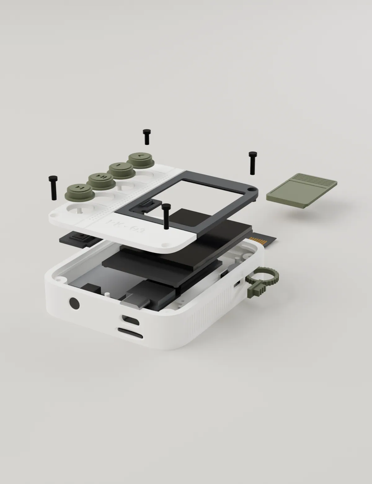
A one piece printed shell, a printed deck with four key caps, a screen band and a slot in the top edge for flat record cards, around bought modules that you wire together. Four black screws on the face hold the deck down. There is no circuit board to order for the player itself.
How it works
Seven ideasFour screws, no inserts. Four M2 button head screws go down through the deck into four M2 nuts. Each nut sits in a slot trap in the side of a screw boss in the shell, slid in from the inside before anything else goes in. Three screws are M2 x 8; the top left boss hangs over the cell and takes an M2 x 5. One of the four also passes through the band.
Modules sit in printed cradles. The cell lies flat in the left half. The jack, the QT Py board, the charger, the DAC board, the encoder and the hold switch each sit on printed rails, fences and blocks. The screen module rests on four posts with a 0.5 foam pad on each, which presses it up into the band.
The screen is a band. The deck is an L shape round a dark band. Changing the screen means printing a different band (and for the two bars a different deck and a screen carrier).
The keys. Four round caps stand through the deck. Each has a flange under the deck that holds it in, and a stem that presses a tact switch on a printed carrier. The carrier snaps onto four split posts under the deck.
Two card slots. The music library is an ordinary microSD card in a push-push socket at the port end, under the USB-C port. Record cards go in a separate slot in the top edge: a printed channel guides a flat card edge first, and eight small springs on the channel floor press up on eight gold pads in the card's underside (section 10). The back is a plain skin: no door, window or latch.
Sound. The DAC board feeds the 3.5 mm jack. The QT Py is a classic ESP32, so it also streams to Bluetooth headphones and speakers, and plays to a docked SP-01 speaker over Bluetooth (section 11).
You solder by hand. Every module is wired to the QT Py board with thin silicone wire (section 06).
The stack
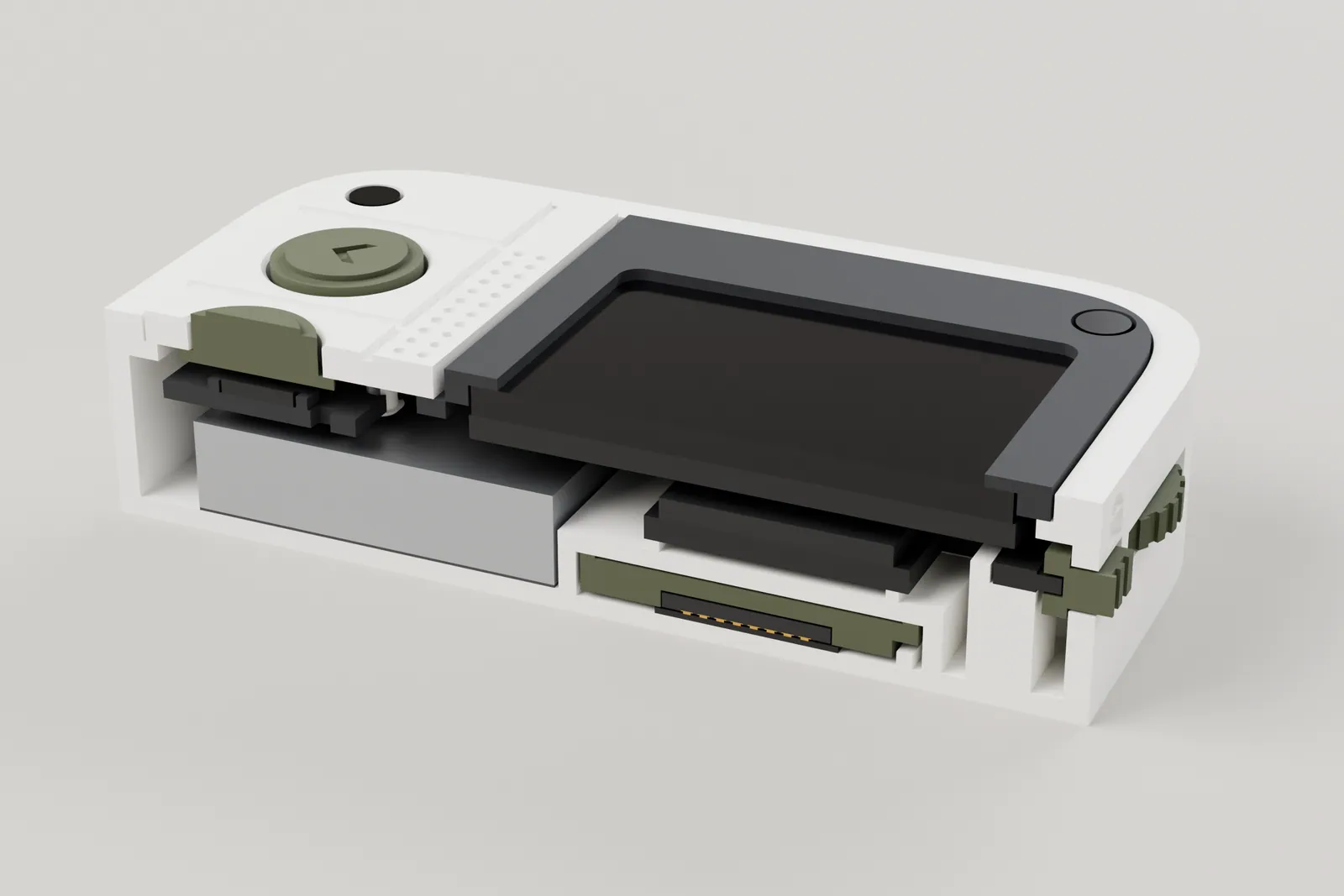
mm above the back| Height | What is there |
|---|---|
| 12.8 to 15.0 | deck and band, 2.2 thick; the deck stands 0.4 above the rim and the caps 0.8 above the deck |
| 12.2 to 14.2 | screen glass, under a 0.8 lip of the band |
| 10.6 to 12.2 | screen module board |
| 9.05 to 12.8 | key carrier, tact switches and cap flanges (left half) |
| 6.2 to 9.4 | QT Py and DAC board on rails over the card channel roof; the nuts at 6.2 to 7.8 |
| 1.6 to 7.8 | the cell on its foam, with swell room to 8.5 (left half) |
| 1.7 to 4.3 | the record card in its channel, resting on the reader's springs (right half) |
| 1.2 to 1.6 | the reader's base, on the channel floor |
| 0 to 1.4 | back skin (1.2 under the channel) |
No speaker and no headphone amplifier: the DAC board drives in-ear monitors directly, and 32 ohm and higher headphones will be quiet through the jack (use Bluetooth for those). Bluetooth is a transmitter only: it sends to headphones and speakers and does not receive from a phone. No MP3, AAC, ALAC, Ogg or Opus. Files above 96 kHz are refused, not resampled.
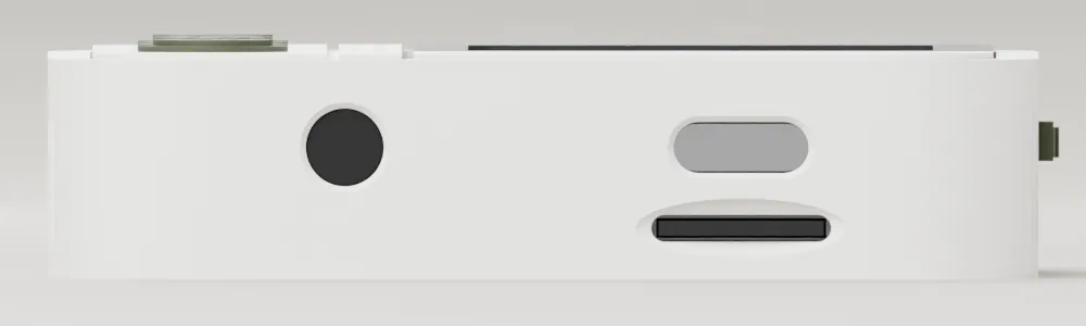
The port end. Three plain openings with small sloped edges and no icons, because the shapes say what they are: the headphone jack, USB-C for charging and flashing, and under it the library microSD slot. The card sits latched about 0.3 inside the end face.
Tools and supplies
What you need besides the parts in section 03. Gather it before you start, so nothing is missing mid-step.
| Item | What it is for |
|---|---|
| Printing | |
| An MSLA resin printer with a build area of at least 196 x 122 mm and 210 mm of height (or a print service) | every printed part; the shell is about 66 x 78 x 15 and the rack 22.2 x 25.8 x 22 |
| A slicer that lets you add supports by hand | supports go only on the face named for each part (section 05) |
| Plain printer paper | levelling the build plate (not card) |
| IPA or resin cleaner, two wash containers, UV cure station | washing (dirty bath, then clean) and post-curing |
| Digital callipers | the exposure test, the 20 mm cube and measuring every bought module |
| Finishing | |
| Flush cutters, hobby knife, a thin wedge scraper | removing supports while the part is green; lifting parts off the plate |
| Wet and dry paper, 400 and 800 grit; a scuff pad | support nubs, fit faces and the finish |
| Pin vise with small drill bits (1.1 mm and up) | clearing screw holes and swabbing small pockets |
| Filler primer and matte paint (spray cans) and masking tape | the finish, one colour per part |
| Electronics | |
| Soldering iron with a fine tip, solder, flux, wire strippers, tweezers | every wire in section 06, including the QT Py back pads |
| Multimeter | checking polarity, the key ladder and continuity before power |
| Heat shrink or kapton tape | insulating the cell leads and joints |
| A steel rule | checking that a card's pads are level (section 10) |
| Card circuit board: a hot plate or hot air tool, solder paste and fine tweezers | soldering the SD NAND chip onto the card board |
| Assembly | |
| A 1.5 mm hex key | the four M2 button head screws |
| Tweezers, a plastic spudger | nuts, foam pads and wires |
| A soft cloth | working on the face and the back without marking them |
| Firmware and cards | |
A computer with ESP-IDF 5.5 (see firmware/README.md) and a USB-C cable | flashing the QT Py board (section 07) |
| A card reader, and a printer for sticker paper | filling record cards and printing their labels (section 10) |
| Safety | |
| Nitrile gloves, eye protection, ventilation | uncured resin, IPA and flying offcuts |
| A safe place to handle the LiPo cell: no piercing, bending or shorting its leads | a damaged or shorted cell can overheat |
Parts
Order the modules first and measure each one before you print the parts that wrap it. Any part matching the spec works; where an example helps it says so. Prices are in Australian dollars for one unit, October 2026, and the list follows your parts tier.
Printed parts
every STL inout/print/, already in its print posePrint the player set, one screen set and, for a build with the record card reader, your cards and the rack; without it, print the slot blank instead. Each file is posed as listed and never lies flat on the plate. Add supports in the slicer only on the face named here. Settings and finishing are in sections 04 and 05.
| File | Part | Qty | Pose (x, y, z) | Supports |
|---|---|---|---|---|
| The player | ||||
| pk01_shell.stl | shell | 1 | x -25, y 15, z 0 | back face toward the plate, tilted 25 and 15 degrees; supports on the back face (it rests on the desk and is sanded) and inside the cavity; two small vents in the back skin and four drains in the slot roof let the pockets drain |
| pk01_key_cap_back.stl | key cap back | 1 | x 35, y 0, z 45 | dish up, tilted 35 degrees; supports under the flange |
| pk01_key_cap_prev.stl | key cap prev | 1 | x 35, y 0, z 45 | as the Back cap |
| pk01_key_cap_play.stl | key cap play | 1 | x 35, y 0, z 45 | as the Back cap |
| pk01_key_cap_next.stl | key cap next | 1 | x 35, y 0, z 45 | as the Back cap |
| pk01_key_carrier.stl | key carrier | 1 | x 30, y 20, z 0 | inside part: any face may carry supports; flat side toward the plate, tilted |
| pk01_wheel_sleeve.stl | wheel sleeve | 1 | x 35, y 0, z 0 | on edge, tilted 35 degrees; supports on the lower face (inside the body) |
| pk01_hold_cap.stl | hold cap | 1 | x 0, y -60, z 0 | outer end up, tilted 30 degrees; supports on the inner face of the flange (inside the body) |
| The screen set | ||||
| pk01_deck.stl | deck | 1 | x 30, y 15, z 0 | face up, tilted 30 and 15 degrees; supports on the underside and the carrier posts only |
| pk01_band_2.0.stl | band 2.0 | 1 | x 30, y 15, z 0 | face up, tilted; supports on the underside, the flange and inside the glass pocket (hidden by the glass) |
| pk01_deck_bar.stl | deck bar | 1 | x 30, y 15, z 0 | bar screen builds only, in place of the deck: as the deck |
| pk01_band_oled_bar.stl | band oled bar | 1 | x 30, y 15, z 0 | 2.08 mono OLED bar builds (Budget): as the 2.0 band |
| pk01_band_225_bar.stl | band 225 bar | 1 | x 30, y 15, z 0 | 2.25 bar builds: as the 2.0 band |
| pk01_carrier_oled_bar.stl | carrier oled bar | 1 | x 30, y 20, z 0 | OLED bar builds: inside part, any face may carry supports |
| pk01_carrier_225_bar.stl | carrier 225 bar | 1 | x 30, y 20, z 0 | 2.25 bar builds: inside part, any face may carry supports |
| pk01_band_1.9.stl | band 1.9 (in out/stl/, with the plain pk01_deck.stl above) | 1 | pose as the 2.0 band | as the 2.0 band; the module posts are placed for the 2.0 board, so give a smaller module its own posts before you print |
| pk01_band_1.69.stl | band 1.69 (in out/stl/, with the plain pk01_deck.stl above) | 1 | pose as the 2.0 band | as the 2.0 band; the module posts are placed for the 2.0 board, so give a smaller module its own posts before you print |
| pk01_band_1.47.stl | band 1.47 (in out/stl/, with the plain pk01_deck.stl above) | 1 | pose as the 2.0 band | as the 2.0 band; the module posts are placed for the 2.0 board, so give a smaller module its own posts before you print |
| Record cards, the rack and the slot blank | ||||
| pk01_card_face.stl | card face | 1 per card | x 210, y 15, z 0 | per card, Budget or Premium: label face up, tilted; supports on the inner face (taped to the medium) |
| pk01_card_frame.stl | card frame | 1 per card | x 30, y 15, z 0 | per card, Budget or Premium: contact face up, tilted; the pocket is a through window; supports on the inner face (against the face half) |
| pk01_card_rack.stl | card rack | 1 | x 25, y 15, z 0 | base toward the plate, tilted; supports on the underside of the base only |
| pk01_slot_blank.stl | slot blank | 1 | x 210, y 15, z 0 | builds without the record card reader only: key cut up, tilted; supports on the cut and the frame side (inside the slot) |
Parts to buy
follows your parts tier| Part | Qty | Where | AUD | Fallback | Checked (2026-11-16) |
|---|---|---|---|---|---|
| Resin for the print set (player with the 2.0 screen set, one card and the rack: 31.0 cm3 printed, 35 percent waste, at A$0.044 per cm3)Resin for the print set (player with the 2.0 screen set, one card and the rack: 31.0 cm3 printed, 35 percent waste, at A$0.044 per cm3)JLC3DP print of the same 13 parts, all but the shell at the A$6 minimum, plus a A$30 parcel | 1 | home print, any tough opaque paintable resin | 1.841.84108.88 | none recorded | not individually checked, 2026-11-16 |
| Abrasives only: dark resin, satin by hand (800 grit and a scuff pad)Filler primer, satin black and one colour (shell, deck, band, caps)Filler primer, satin black and one colour (shell, deck, band, caps) | 1 | any hardware store (spray cans) | 3.0021.0021.00 | none recorded | not individually checked, 2026-11-16 |
| Wheel sleeve and hold cap (printed, in the resin line)Wheel sleeve and hold cap (printed, in the resin line)Machined aluminium wheel sleeve and brass hold cap | 1 | home print | 0.000.0015.00 | none recorded | not individually checked, 2026-11-16 |
| Adafruit QT Py ESP32 Pico from Pakronics (AU)Adafruit QT Py ESP32 Pico (#5395, ESP32-PICO-V3-02: Bluetooth Classic and BLE, 8 MB flash, 2 MB PSRAM, USB-C, 22.0 x 17.9)Adafruit QT Py ESP32 Pico (#5395, ESP32-PICO-V3-02: Bluetooth Classic and BLE, 8 MB flash, 2 MB PSRAM, USB-C, 22.0 x 17.9) | 1 | Little Bird (AU) | 30.0731.5531.55 | Little Bird AF-5395, A$31.55, 28 at supplier (catalogue page read) | 2026-11-16: Core Electronics in stock, A$28.30 (search page read). Little Bird in stock, A$31.55 |
| USB-C mini Li-ion charger module, 600 mA CC/CV, 10 x 7.5 x 5.2 (its receptacle is not used: it takes 5 V from the QT Py's 5V pad)USB-C mini Li-ion charger module, 600 mA CC/CV, 10 x 7.5 x 5.2 (its receptacle is not used: it takes 5 V from the QT Py's 5V pad)USB-C mini Li-ion charger module, 600 mA CC/CV, 10 x 7.5 x 5.2 (its receptacle is not used: it takes 5 V from the QT Py's 5V pad) | 1 | AliExpress (search: type-c mini lithium charger board) | 1.501.501.50 | none recorded | not individually checked, 2026-11-16 |
| STEMMA QT / Qwiic JST SH 4-pin lead, 100 mm (the wheel's A and B on its two data wires)STEMMA QT / Qwiic JST SH 4-pin lead, 100 mm (the wheel's A and B on its two data wires)STEMMA QT / Qwiic JST SH 4-pin lead, 100 mm (the wheel's A and B on its two data wires) | 1 | Little Bird (AU) | 1.501.501.50 | Little Bird has the 150, 200, 300 and 400 mm leads too | 2026-11-16: Little Bird AF-4399 STEMMA QT cable, A$2.15, 16 in Sydney |
| 2.08 mono OLED bar (ER-OLED0208-1W, 256 x 64, BuyDisplay) and a 30 pin 0.5 FPC adapter board: the Budget screen, with the bar deck, band and carrier prints2.0 inch ST7789 240 x 320 IPS SPI module, PCB 35 x 58, no connector fitted (Waveshare 2inch LCD Module)2.0 inch ST7789 240 x 320 IPS SPI module, PCB 35 x 58, no connector fitted (Waveshare 2inch LCD Module) | 1 | Waveshare via an AU stockist | 18.0022.0022.00 | Not confirmed. Little Bird WS-19888 (A$21.50, in stock) is the Pico version with a different PCB, not a drop-in | not stock checked, 2026-11-16 |
| GY-PCM5102 PCM5102A I2S DAC board, 32 x 17 (do not fit its jack or header pins)GY-PCM5102 PCM5102A I2S DAC board, 32 x 17 (do not fit its jack or header pins)GY-PCM5102 PCM5102A I2S DAC board, 32 x 17 (do not fit its jack or header pins) | 1 | AliExpress (search: GY-PCM5102) | 5.005.005.00 | Adafruit PCM5102 (AF-6250): Little Bird A$9.70, Core A$8.95, in stock (search pages read). Different board size from the GY-PCM5102 (32 x 17), so check the bay | 2026-11-16: no GY-PCM5102 at an AU source found; AliExpress only |
| Optional, record card reader: a strip of eight spring contacts at 1.1 pitch that lies flat under the card (about 12.0 x 11.0 x 0.4; the exact part is confirmed by measurement)Optional, record card reader: a strip of eight spring contacts at 1.1 pitch that lies flat under the card (about 12.0 x 11.0 x 0.4; the exact part is confirmed by measurement)Optional, record card reader: a strip of eight spring contacts at 1.1 pitch that lies flat under the card (about 12.0 x 11.0 x 0.4; the exact part is confirmed by measurement) | 1 | Mouser AU or element14 AU | 2.003.503.50 | none recorded | not individually checked, 2026-11-16 |
| Push-push microSD socket (flush latching, Molex 104031-0811 class) on a small breakout, for the library slotPush-push microSD socket (flush latching, Molex 104031-0811 class) on a small breakout, for the library slotPush-push microSD socket (flush latching, Molex 104031-0811 class) on a small breakout, for the library slot | 1 | AliExpress (search: push push micro SD breakout) | 2.002.002.00 | Adafruit AF-1660 microSD socket, Little Bird A$4.10, 100 at supplier (a different socket, check the footprint) | not stock checked, 2026-11-16: AliExpress listing only |
| microSD card, 32 to 128 GB, for the library slotmicroSD card, 32 to 128 GB, for the library slotmicroSD card, 32 to 128 GB, for the library slot | 1 | any electronics store | 12.0012.0012.00 | none recorded | not individually checked, 2026-11-16 |
| PJ-320 class 3.5 mm panel jack (pack of 10)PJ-320 class 3.5 mm panel jack (pack of 10)PJ-320 class 3.5 mm panel jack (pack of 10) | 1 | AliExpress (search: PJ-320A) | 2.002.002.00 | none recorded | not individually checked, 2026-11-16 |
| SIQ-02FVS3 thumbwheel encoder with pushSIQ-02FVS3 thumbwheel encoder with pushSIQ-02FVS3 thumbwheel encoder with push | 1 | AliExpress or LCSC | 4.004.004.00 | none recorded | not individually checked, 2026-11-16 |
| 5.2 x 5.2 SMD tact switch, 1.5 tall (TS-1187A class, pack; 4 used)5.2 x 5.2 SMD tact switch, 1.5 tall (TS-1187A class, pack; 4 used)5.2 x 5.2 SMD tact switch, 1.5 tall (TS-1187A class, pack; 4 used) | 1 | AliExpress or Jaycar | 2.002.002.00 | none recorded | not individually checked, 2026-11-16 |
| MSK12C02 SPDT slide switch (pack)MSK12C02 SPDT slide switch (pack)MSK12C02 SPDT slide switch (pack) | 1 | AliExpress (search: MSK12C02) | 2.002.002.00 | SparkFun SPDT slide switch SF-COM-09609, Little Bird A$0.80, 1759 in Sydney (different body, check the cut-out) | not stock checked, 2026-11-16: AliExpress listing only |
| Resistors for the key ladder, battery divider and the record card detect (1 M), 30 AWG silicone wire, two coloursResistors for the key ladder, battery divider and the record card detect (1 M), 30 AWG silicone wire, two coloursResistors for the key ladder, battery divider and the record card detect (1 M), 30 AWG silicone wire, two colours | 1 | Jaycar or Altronics | 3.003.003.00 | none recorded | not individually checked, 2026-11-16 |
| 602560 LiPo, 1000 mAh, protection board, JST PH 2-pin (6 x 25 x 60, no bigger than 25.5 x 61 x 6.2)602560 LiPo, 1000 mAh, protection board, JST PH 2-pin (6 x 25 x 60, no bigger than 25.5 x 61 x 6.2)AU-stocked 602560 class 1000 mAh LiPo (check the size) | 1 | AliExpress (search: 602560 1000mAh) | 7.007.0018.60 | Not checked at an AU source. Little Bird LB-00238 (1200 mAh, A$18.60, in stock) is the nearest stocked cell, size unconfirmed | not checked at an AU source (AliExpress listing only), 2026-11-16 |
| microSD card, 8 to 32 GB, for the Budget record card (reader builds only)microSD card, 8 to 32 GB, for the Budget record card (reader builds only)Premium record card: 0.4 card PCB 11 x 15, ENIG (JLCPCB, 5 boards) and SD NAND 1 GB LGA-8 (LCSC, 5) | 1 | any electronics store | 6.006.0035.00 | none recorded | not individually checked, 2026-11-16 |
| Plain paper labels under clear tapePrintable matte vinyl sticker paper, A4 (face, spine and back labels)Printable matte vinyl sticker paper, A4 (face, spine and back labels) | 1 | Officeworks | 1.008.008.00 | none recorded | not individually checked, 2026-11-16 |
| M2 ISO 7380 button head, black (three M2 x 8, one M2 x 5 for the top left boss) and M2 DIN 934 nuts (4), packsM2 ISO 7380 button head, black (three M2 x 8, one M2 x 5 for the top left boss) and M2 DIN 934 nuts (4), packsBlack stainless M2 x 8 and M2 x 5 button heads and nuts from an AU fastener shop | 1 | AliExpress (search: M2 button head black) | 4.004.0012.00 | none recorded | not individually checked, 2026-11-16 |
| Foam and tape: 0.5 pads for the screen posts, 0.2 foam under the cell, thin double-sided tapeFoam and tape: 0.5 pads for the screen posts, 0.2 foam under the cell, thin double-sided tapeFoam and tape: 0.5 pads for the screen posts, 0.2 foam under the cell, thin double-sided tape | 1 | any hardware store | 4.004.004.00 | none recorded | not individually checked, 2026-11-16 |
| Shipping, one small AU parcel and the BuyDisplay post (AliExpress free)Shipping, AU parcelsShipping, AU parcels | 1 | Core Electronics or DigiKey AU | 12.0010.0015.00 | none recorded | not individually checked, 2026-11-16 |
| Total | 123.91153.89329.53 |
Budget preset: AUD 124 for one unit. The mono OLED bar, the cheapest line for each part and a home print.
Mid preset: AUD 154 for one unit. The 2.0 inch colour module, listed suppliers and a home print.
Premium preset: AUD 330 for one unit. A print service casing, machined sleeve and cap, black stainless screws and card circuit boards for the cards.
Approximate cost for one player, the record card reader, one record card and the rack, from supplier listings in October 2026. Without the record card reader the totals are AUD 115, 136 and 271 for Budget, Mid and Premium. The AU parcel line covers the Core Electronics and DigiKey orders; the AliExpress lines ship free but slowly. Resin is counted at AUD 0.044 per cm3 of printed volume plus 35 percent waste; the bottle, IPA, gloves and tools are treated as owned. Several parts ship in packs, so the first unit costs more than later ones.
Every module is modelled at a nominal size. Order one of each and measure before a second order: the screen module first (board 35 x 58, panel 2.0 thick), then the QT Py ESP32 Pico (22.0 x 17.9, the height of the parts on both faces, and where its antenna ends), the card reader's contact strip (base thickness and spring height), the push-push library socket and the GY-PCM5102 (32 x 17, with its jack and header pins left off). The DAC is the GY-PCM5102 because nothing smaller with a PCM5102A was found: the Adafruit boards are 20 mm wide and do not fit the 17 wide space beside the slot channel. There is no room for a headphone amplifier, and the PCM5102A drives in-ear monitors directly.
The reader is a strip of eight spring contacts at 1.1 pitch that lies flat under the card and presses on its gold pads. It lies on the channel floor with nothing under it, and its 0.4 base puts the card seat at 1.6. The exact part is being confirmed by measurement: before you order a second one, measure the first one's base thickness and spring height. Solder 30 AWG wires to its eight tails.
The QT Py has no LiPo charger and no native USB (its USB-C goes to a serial chip), so the list adds a small charger module fed from the board's 5V pad and a STEMMA QT lead that carries the wheel's two signals. Record cards are optional (section 00): without the reader, leave out the two lines marked Optional, the record card and the rack, and print the slot blank. Budget cards carry a standard microSD taped into the printed card; Premium cards carry the 0.4 card board, 11 x 15, with an SD NAND (outline and pads in out/card/). Each extra Budget card costs the microSD plus about AUD 0.10 of resin; each extra Premium card about AUD 7. The two bar screens are bare glass with a flex tail: they also need a flex to pin adapter board (30 pin for the OLED, 12 pin for the 2.25 bar) and a printed screen carrier.
Print setup: calibrate first
Every fit in this kit depends on your printer printing true. Do this list before you print a single part: each item, skipped, can stop a part from fitting.
- Level the build plate with plain printer paper, not card. Loosen the plate, lay the paper on the screen, press the plate down evenly, tighten it, then set Z = 0.
- Use 0.05 mm layers. The engraving is 0.4 deep and the dot strip is 0.6 deep, so thicker layers lose them.
- Calibrate the exposure for your resin and room temperature with an exposure test print. Choose the time at which 0.8 mm features print crisp, a 0.8 gap stays a gap, and a 1.0 mm post fits a 1.2 mm hole.
- Check the size. Print a 20 mm cube and confirm X and Y are within 0.05 mm. Every fit tolerates +/-0.2 mm, but the card in its channel has only 0.3 a side, so keep the cube honest.
- Keep the resin warm, about 25 C, and stir it before every print.
- Measure the bought modules (the table below) before you print the parts that wrap them.
The values the model uses
all nominal until measured| What | Value in the model | Where it is set |
|---|---|---|
| Screen module board, panel and where its active area sits | 35 x 58 x 1.6; panel 34.6 x 45.8 x 2.0; active area 30.6 x 40.8 | MOD |
| Reader contact strip: base, spring height and the card seat | base 12.0 x 11.0 x 0.4; leaves 0.35 above the base; card seat at 1.6 above the back; 8 contacts at 1.1 pitch | READER |
| Push-push library microSD socket and its breakout | 14.0 x 15.2 x 1.85; breakout 15.6 x 18.0 x 1.0; card latched 0.3 inside the end face | PSD |
| GY-PCM5102 board and tallest part (jack removed) | 17 x 32 x 1.6; parts 1.4 | DAC |
| QT Py ESP32 Pico: board, USB-C shell and part heights | 17.9 x 20.7 x 1.0; USB-C stands 1.3 past the edge; top parts 2.2; back parts 1.7 | MCU |
| Charger module | 7.5 x 10.0 x 5.2 | CHG |
| 602560 cell, the largest size the space takes | 25.5 x 61.0 x 6.2 | CELL |
| Encoder dial and body | dial 11.0 x 2.0; body 8.5 x 10.6 x 2.0 | WHEEL |
| Tact switch and plunger | 5.2 x 5.2 x 1.0; plunger 0.8 x 0.5; travel 0.25 | TACT |
| Hold switch body and actuator | 6.7 x 2.6 x 1.4; actuator 1.6 x 1.5 x 1.0 | HOLD |
| Bar screens: glass, view area and flex width | OLED 19.0 x 60.5 x 1.6; 2.25 bar 17.9 x 62.5 x 2.3 | BAR_SCREENS |
| M2 button head and nut | head 3.5 x 1.3, length 8 (5 for the top left); nut 4.0 across flats x 1.6 | M2 |
Change it in params.py. Run python print_files.py --dfm to rewrite the print set, then pytest tests (always pytest tests: a bare pytest also collects the firmware's vendored folders). Print the new files only if every test passes; a failing test names the fit that no longer holds.
The values that matter most are the reader's contact strip (the stack under the card closes with only 0.1 to spare), the screen module (its stack margin to the QT Py's top parts is only 0.2) and the DAC (0.4 to the screen module tail).
Print and finish the parts
Every STL is already in its print pose, tilted, and never flat on the plate. Add supports by hand only on the face named for the part in section 03: every cosmetic face looks away from the plate. The shell is the big one; print it first and fit it before you print the rest.
Print order
fit as you go- The shell. Print it, wash it, cure it, and fit a nut into each of the four side slots. Check the slots, the QT Py rails, the cell space, the jack saddle and the slot channel against the bought parts. A part that does not fit now is a measuring or exposure problem to fix before you print more.
- The screen set, the key caps and the key carrier. With the deck on the shell, check the caps drop into their holes and the band lies in its pocket.
- The wheel sleeve and the hold cap. Both are small. Check the sleeve presses onto the encoder dial (a 0.05 a side press fit) and the cap clips over the switch actuator.
- A card, then the rack, or the slot blank. Print one card first (section 10) and slide it into the channel to check the fit: it must go the whole way with a light push. Without the record card reader, print the slot blank instead and press it in.
Supports, and what to do about each
only on hidden faces- Shell. Its back face goes toward the plate, tilted 25 and 15 degrees. Put supports on the back face (it rests on the desk and is sanded) and inside the cavity. Two small vent holes in the back skin and four drains in the channel roof stop the pockets sealing against the film: keep them open. The slot channel drains through its mouth and the finger notch.
- Deck, band and the bar decks. Face up, tilted. Supports on the underside, the flange and inside the glass pocket (hidden by the glass). Never on the face.
- Key caps. Dish up, tilted 35 degrees, supports under the flange only. Never support the dish or its glyph.
- Card halves, slot blank and rack. The label half has its label face up and the contact half its contact face up, both tilted, with supports on the inner faces that are joined together; the pocket in the contact half is a through window. The slot blank has its key cut up, with supports on the cut and the frame side inside the slot. The rack stands on its base, tilted, with supports on the underside of the base only.
- Key carrier and screen carriers. Inside parts: any face may carry supports.
- Wheel sleeve and hold cap. Supports on the faces inside the body only. Peel them gently.
A few pockets in the shell and the two bar bands hold a few cubic millimetres of resin that cannot vent to a hidden face (each under 10 mm3): the two screw clearance holes under the right nut slots, a corner between the right DAC rail and the reader bay wall, a corner between the bay wall and the stop wall, the top left corner by the cell rib, the space under the shelf by the bottom left boss and, on the bar bands, the top left corner of the glass pocket. Swab them after the first wash.
Finishing
after the fit check- Wash in two baths (dirty, then clean) of IPA or the resin's own cleaner. Blow out the vents, the nut slots and the screw holes.
- Take the parts off the plate with a thin wedge scraper and remove supports while the parts are still green. Let them dry fully.
- Cure under UV for the resin's stated time, turning each part halfway. Do not over-cure the thin parts: the key carrier and the cards.
- Sand the support nubs flat (400, then 800 grit), and keep the sanding off the fit faces: the slot channel, the card pocket walls and edges, the deck holes, the cradles.
- Prime with a thin, even coat of grey filler primer, then sand it lightly at 800 grit.
- Paint with a flat matte finish, one colour per part, from the list below. Paint after the fit check, never before it, and keep paint off the fit faces: a coat adds a few hundredths of a millimetre.
The mark and the key glyphs are engraved in the part's own colour and read by shape. Never fill an engraving with another colour. The three port openings carry no icons: their shapes say what they are. If a key cap or the sleeve gets stiff after painting, thin the paint, not the part.
Paint list
flat matte, one colour per part (the example is paper white with olive)| Part | Example colour |
|---|---|
| Shell, deck, slot blank, card rack | paper white |
| Band (the screen band) | charcoal |
| Key caps, wheel sleeve, hold cap | olive |
| Record cards | any single colour per card, so they are easy to tell apart; mask the window and keep paint out of the channel |
| Key carrier, screen carrier | not painted: they are inside |
Wiring by module pin
Every module is wired to the Adafruit QT Py ESP32 Pico with 30 AWG silicone wire, two colours. The table says which pad each wire goes to, on both ends. Wire the modules in the order of the assembly steps, but read the whole table first.
The firmware reads its pins from one header, firmware/components/pk_board/include/pk_pins_qtpy.h. The table below is the assignment that header holds: wire exactly this. The QT Py has 14 usable GPIOs and the player uses all 14, so there is no spare pin. Every wire has two ends: do not guess a pad from its colour.
Every wire, pad by pad
QT Py pad names are the silkscreen names| From | To (QT Py) | What it carries |
|---|---|---|
| Power, charging and ground (one star point: the QT Py 3V3 and GND pads) | ||
| Charger module IN+ and IN- | 5V pad and GND pad | USB power for charging. The charger's own USB-C receptacle is not used |
| Charger OUT+, and the cell + (protection board B+) | BAT+ pad (back) | the cell, charged by the module and feeding the board; also the top of the sense divider |
| Charger OUT-, and the cell - (protection board B-) | BAT- pad (back) | battery return |
| Divider: 100 k from cell + to a node, 100 k from the node to GND, 100 nF from the node to GND, and 100 k from the 5V pad to the node | SCL pad (GPIO33) | battery and USB sense on one pin: 1.0 to 2.1 V on battery, 2.6 to 3.0 V with USB in. Above 2.35 V the player knows it is on USB |
| Screen module (SPI) Bar screens: use the flex adapter board's pins of the same names | ||
| DIN | MO pad (GPIO13) | data to the screen and both card sockets |
| CLK | SCK pad (GPIO14) | clock, shared with both card sockets |
| CS | A3 pad (GPIO15) | screen chip select |
| DC | BOOT button pad (GPIO0) | data or command. The board holds this pin high at power-up: check the module's DC has no pull-down |
| RST, BL, VCC | 3V3 | reset held high, backlight always on (no dimming), power |
| GND | GND | |
| Library microSD socket (push-push, on its breakout), SPI mode | ||
| CS (DAT3) | A2 pad (GPIO27) | library card chip select |
| CMD | MO pad (GPIO13) | shared with the screen |
| CLK | SCK pad (GPIO14) | shared with the screen |
| DAT0 | A0 pad (GPIO26) | data back from the cards, shared by both sockets. Not on the MI pad: a card holds its DAT0 high, which would set a boot strap |
| DAT1, DAT2 | 3V3 through 10 k each | unused lines held high |
| VDD / VSS | 3V3 / GND | |
| Record card reader (the spring contact strip), eight tails, SPI mode. Optional | ||
| Pin 2 (CS) | A1 pad (GPIO25), and 1 M to GND | record card chip select. It is also the card detect: a seated card holds this line high through its own pull-up, the 1 M keeps it low when there is no card |
| Pin 3 (CMD) | MO pad (GPIO13) | shared |
| Pin 5 (CLK) | SCK pad (GPIO14) | shared |
| Pin 7 (DAT0) | A0 pad (GPIO26) | shared |
| Pin 4 (VDD) / pin 6 (VSS) | 3V3 / GND | |
| Pin 1 (DAT2), pin 8 (DAT1) | 3V3 through 10 k each | unused lines held high |
| GY-PCM5102 DAC board (I2S) | ||
| BCK | SDA pad (GPIO4) | bit clock |
| LCK | RX pad (GPIO7) | word clock |
| DIN | MI pad (GPIO12) | audio data. This pin is a boot strap: the DAC input has no pull-up, so it reads low at reset, which is what the board needs |
| SCK | GND | no master clock: the board makes its own (check the seller's drawing for the solder pad) |
| VIN, GND | 3V3, GND | power (check the board's 3.3 V solder bridge) |
| Board solder pads L, R, GND | jack: tip, ring, sleeve | line out to the headphone jack; find tip and ring with a plug and the multimeter |
| Wheel encoder (SIQ-02FVS3), through a STEMMA QT lead plugged into the board's socket | ||
| A | yellow wire, SCL1 (GPIO19) | quadrature A, internal pull-up |
| B | blue wire, SDA1 (GPIO22) | quadrature B, internal pull-up |
| Common | black wire, GND | the red 3V3 wire is cut back and left unconnected |
| Keys, wheel push and hold: one ADC pin, the TX pad (GPIO32) | ||
| 22 k from 3V3 | TX pad (GPIO32) | the ladder node; the idle level is 3.3 V |
| Play key, then 2.2 k | to the node, other side to GND | about 0.30 V when pressed. The lowest level, so Play wakes the player from deep sleep |
| Back key, then 5.6 k | to the node, other side to GND | about 0.67 V |
| Prev key, then 12 k | to the node, other side to GND | about 1.16 V |
| Next key, then 22 k | to the node, other side to GND | about 1.65 V |
| Encoder push switch, then 39 k | to the node, other side to GND | about 2.11 V |
| Hold slide: common to GND, one throw then 62 k | to the node | about 2.43 V while hold is on |
With the cell not yet connected, the multimeter should read: 3V3 to GND open (no short); the TX pad to GND about 22 k with no key pressed, and the table's resistance in parallel with 22 k with each key held. If you build without the record card reader, nothing connects to the A1 pad. The QT Py back pads are small: tin the wire first, then touch it to the pad, and check the neighbouring pads for bridges. The cell and BAT pads are polarity sensitive. Reversed, the board and the cell are destroyed. Keep wires away from the end of the board opposite the USB-C: the antenna is there.
Firmware: flash the QT Py board
Flash the QT Py on the bench before you put anything in the shell, so a dead board costs you nothing else. The board takes the firmware over its own USB-C port through its USB to serial chip, with no battery fitted.
The firmware in firmware/ now targets the classic ESP32 of the QT Py (idf.py set-target esp32) and takes its pins from pk_pins_qtpy.h. It has both cards on the shared SPI bus, the record card detect on the A1 pad, the key ladder, the wheel on the STEMMA pins, the ST7789 screen, the Bluetooth (A2DP) source and the docked behaviour. It builds and its host tests pass, but nothing has run on this hardware: expect to find and fix things at power-up. The screens are chosen in config.txt (below) and the full-screen layout is drawn for the 2.0 inch 240 x 320 module and scaled for the 1.9, 1.69 and 1.47; there is no USB storage mode (the QT Py's USB-C is a serial chip, not the ESP32's own USB: use a card reader). firmware/README.md lists what is unmeasured and what is not written.
- Install ESP-IDF 5.5 as
firmware/README.mdsays. - Set the pins. The firmware takes its pins from
pk_pins_qtpy.h, which matches the table in section 06, and the screen settings from the screen you built (config.txtbelow). - Build and flash with the QT Py on a USB-C cable:
If the board does not appear as a serial device, hold its BOOT button, tap its reset button, then release BOOT, and run the flash again.idf.py set-target esp32 idf.py build idf.py flash monitor - Read the log. It should show the board starting, the library card (size and file system), the screen, the DAC and the Bluetooth stack coming up. A missing library card is reported on the screen, not fatal; a missing record card reader is not reported at all, because it is detected only when a card is pushed in.
config.txt
on the library card, every key optional# PK-01 settings. Lines are key = value. Delete a line to use the default.
screen = auto # auto, oled, ips (auto is ips)
ips_size = auto # ips: auto (2.0), 2.0, 1.9, 1.69, 1.47, 2.25 (the narrow bar)
ips_driver = auto # 2.25 bar only: auto, st7789p3, nv3023b
volume_limit = -6 # dB, 0 is the loudest
start_volume = -30 # dB at power-on
brightness = 70 # percent
screen_timeout = 15 # seconds while playing
sleep_after = 10 # minutes paused, 0 is never
music_folder = /Music # / for the whole card
sort_ignore_the = yes
gapless = yesBad values and unknown keys are logged and ignored. The volume at power-on is never louder than volume_limit. With the backlight wired to 3V3 the brightness setting has no effect. Set screen = oled for the 2.08 inch mono bar (the Budget screen) and ips_size to match the colour module you fitted; with nothing set the player drives a 2.0 inch 240 x 320 ST7789. The keys audio and hp_mode of the earlier board are accepted and ignored: this build has one DAC.
Assembly
Fourteen steps, in the order the model goes together. Each step has a check: do it before you go on. Step 1 and the card in step 14 belong to the optional record card reader.
Connect the cell last, with the multimeter checks done, and with its polarity checked twice. Never leave the cell connected while you solder. A shorted LiPo can overheat.
-
01
Fit the card reader (optional)
Shell, spring contact strip, 8 wires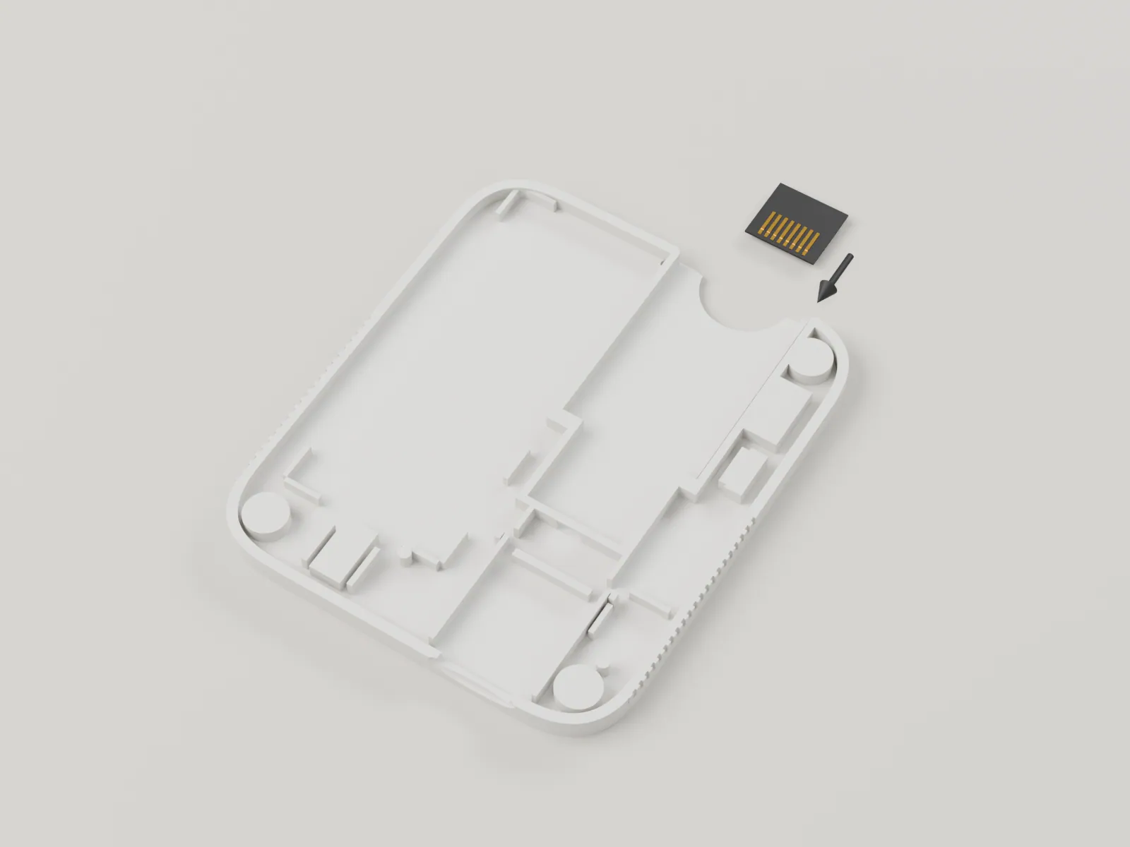
Skip this step if you build without the record card reader: print the slot blank and press it in at step 14. Otherwise solder a 30 AWG wire to each of the eight tails of the contact strip (section 06), about 80 mm long.
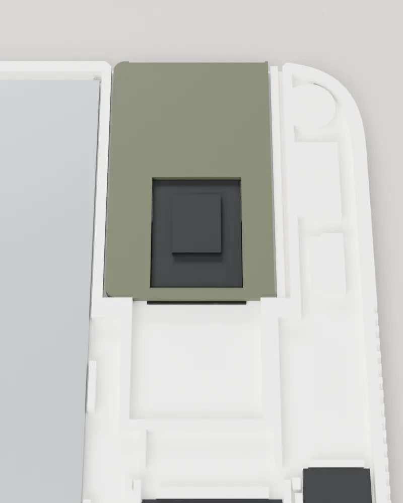
Lay the shell on the cloth, cavity up, port end toward you. The strip lies flat on the floor of the slot channel in the top edge with its springs facing up and its tails toward the inside of the shell. Slide it in through the mouth of the slot, tails first, until its rear edge meets the end of the channel, and lay the wires in the bay behind the two stop shoulders, feeding them out through the wire gate, a 4 mm wide opening in the bay's front wall on the slot's centre line, then on toward the QT Py. The picture shows the shell cut open above the channel so the strip is visible; yours has its roof.
The reader lies flat and level on the channel floor, its springs stand about 0.35 above the base and none is bent or twisted, and the eight wires lie in the bay behind the shoulders. A card laid on it (step 14) must still slide in freely.
-
02
Slide the nuts into the screw bosses
Shell, 4 x M2 nut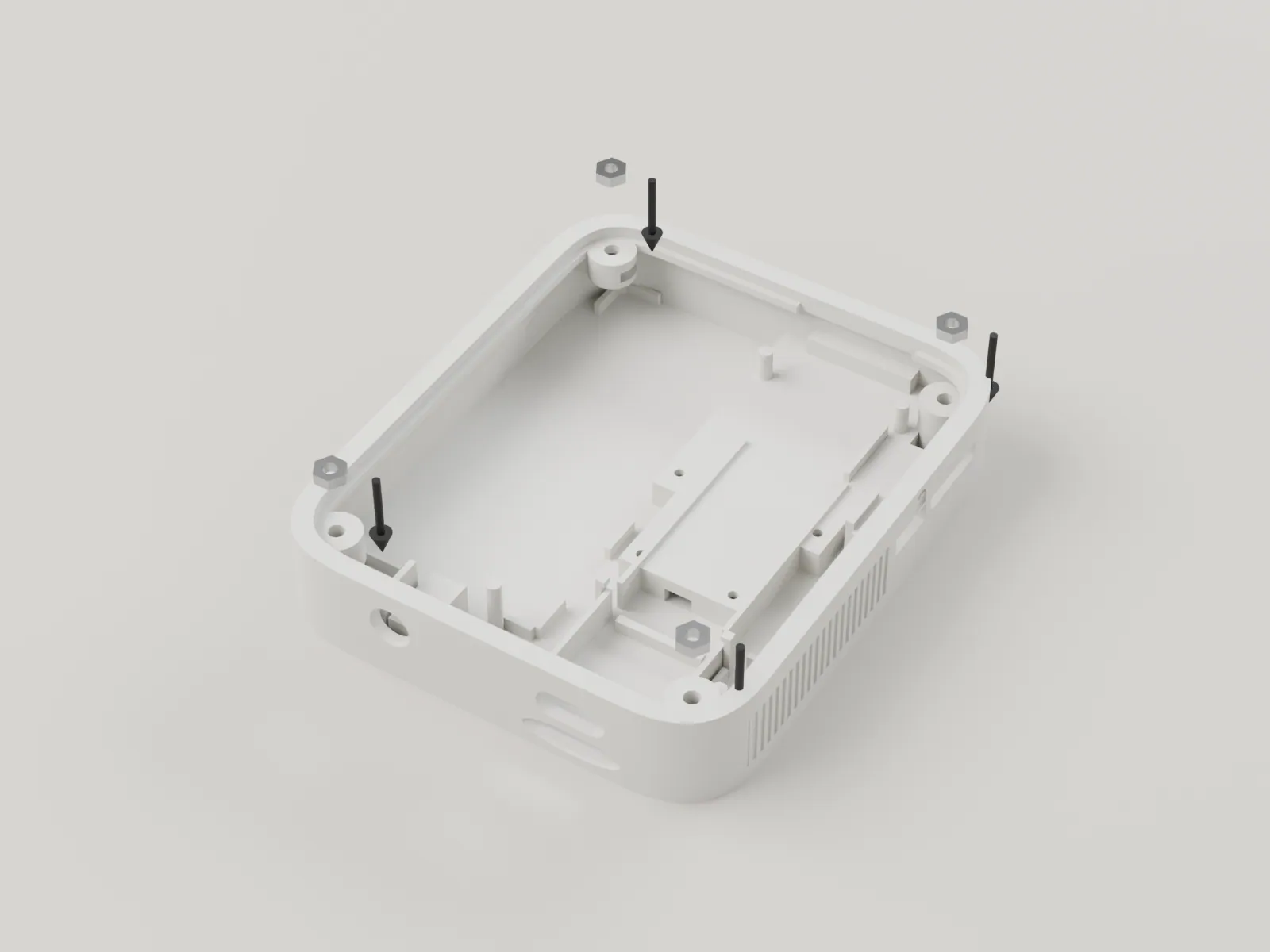
Lay the shell on the cloth, cavity up, port end toward you. Each of the four screw bosses has a slot cut in its side, open toward the inside of the body: three at 6.2 to 7.8 above the back, and the top left one higher, at 9.6, because that boss hangs over the cell. Slide an M2 nut flat into each slot until it stops against the boss.
Each nut sits flat in its slot with its hole over the boss's screw hole, and cannot fall out when you tip the shell. If a nut will not go in, swab the slot and check the print was not over-exposed.
-
03
Lay the cell on its foam
Shell, cell, 0.2 foam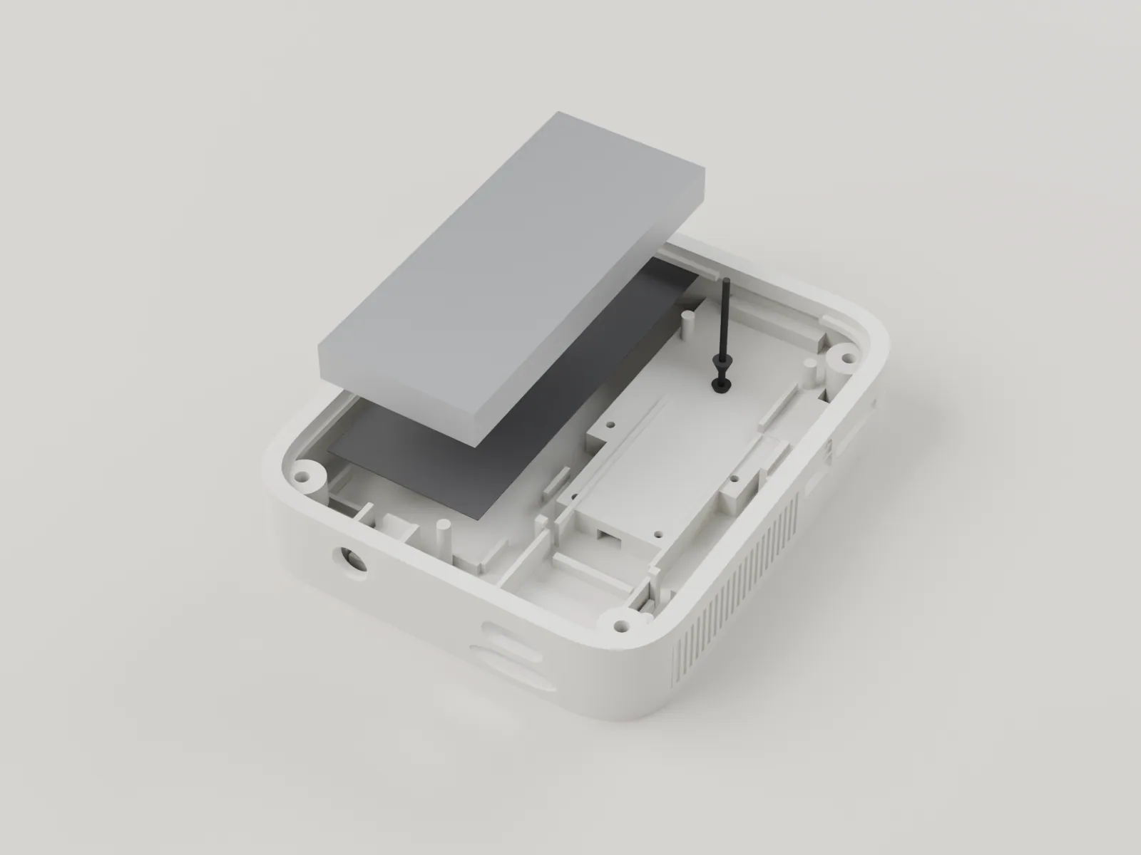
Lay the 0.2 foam on the floor of the left half of the shell. Set the 602560 cell on it with its protection board and lead at the port end. Tape the lead flat along the wall, away from the jack and the screw holes.
The cell lies flat between the wall and the slot channel without being forced, and the lead leaves at the port end. The space takes at most 25.5 x 61.0 x 6.2, and the top left boss clears the cell by about 0.1 when the cell swells.
-
04
Fit the library socket, the jack, the hold switch and the encoder
Library socket and breakout, jack, hold switch, encoder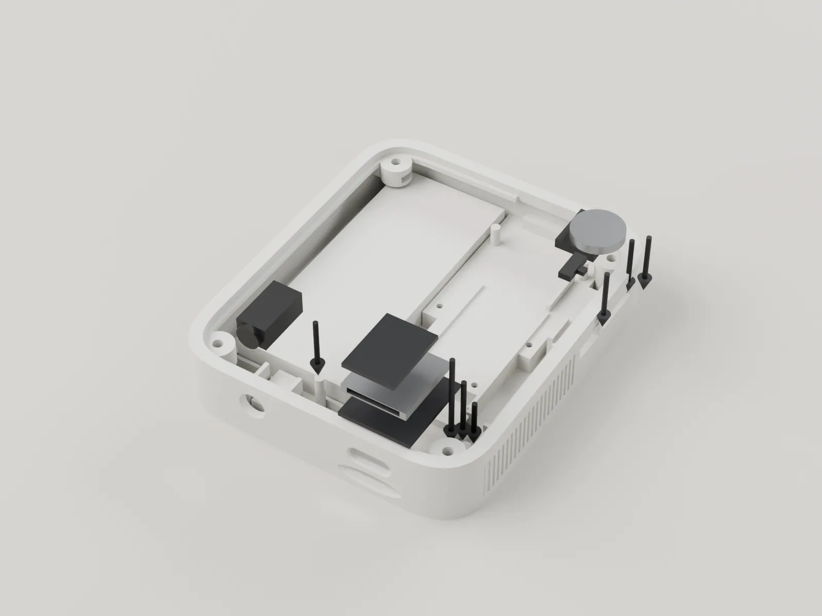
Wire these four first (section 06), then fit them. The library microSD socket sits on its breakout board at the port end, with its card slot toward the end face, in the same column as the USB-C port above it; set the board on the back skin between its fences. The jack sits in its saddle between two cheeks at the port end, with its nose through the round opening. The hold switch sits on its pillar on the right edge with its actuator toward the slot in the right wall. The encoder body sits in its block at the top right with its dial facing the slot in the right wall.
The jack nose is flush with its opening, the library socket's slot lines up with the long opening at the port end, the switch actuator lines up with its slot in the right wall, and the encoder dial lines up with the slot above it.
-
05
Fit the QT Py, the charger and the DAC board
QT Py ESP32 Pico, charger module, GY-PCM5102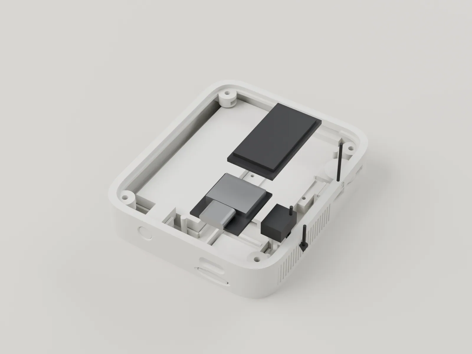
The QT Py sits at the port end on two rails with its USB-C port in the opening, held by two small hooks at its far corners, over the library socket. The charger module sits to its right, on a 0.2 foam pad on the back skin, between its fence and the stop behind it. The DAC board sits above them on two rails. Before fitting, solder the wires to the QT Py's back pads (BAT+ and BAT-), because they run under the board, and plug the STEMMA QT lead into its socket.
The USB-C port is in line with its opening and a cable mates fully. The DAC board lies flat on its rails, about 0.5 from the QT Py's antenna end, and nothing touches the screen's space above (the margin is 0.4).
-
06
Wire everything to the QT Py
Wires, resistors, 22 k and 100 k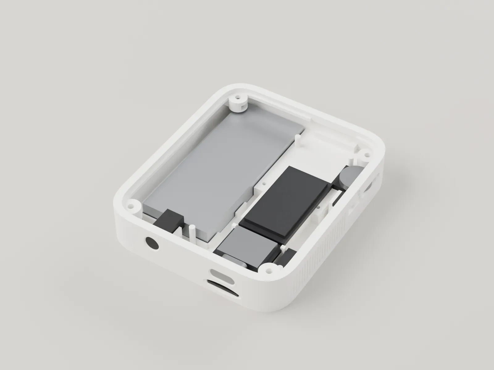
Make the connections in section 06, one module at a time, and tick them off as you go. Keep wires flat along the walls and over the channel roof, short and tied back, so nothing is trapped by the deck. Keep them off the antenna end of the QT Py. Insulate every joint. Solder the ladder resistors in a tight bundle at the key carrier side.
The multimeter checks in section 06 pass. The cell is still not connected.
-
07
Seat the screen
Screen module, 4 foam pads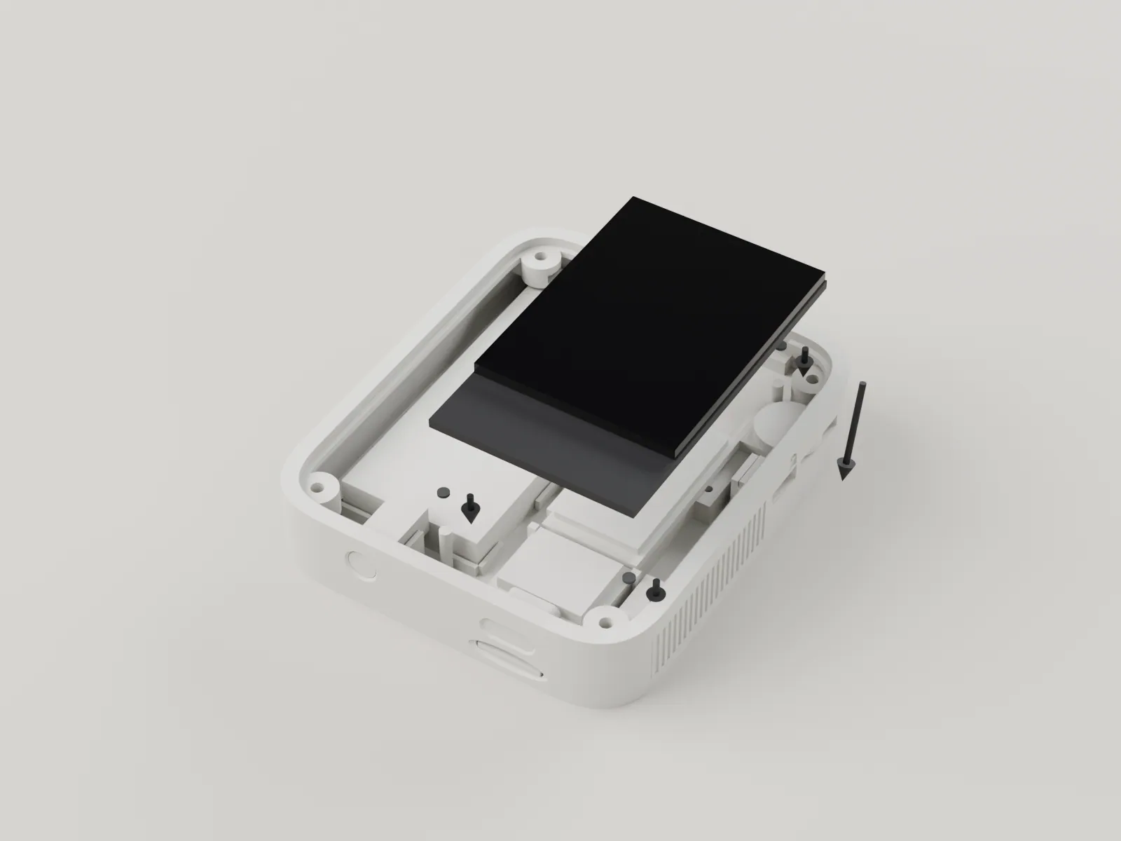
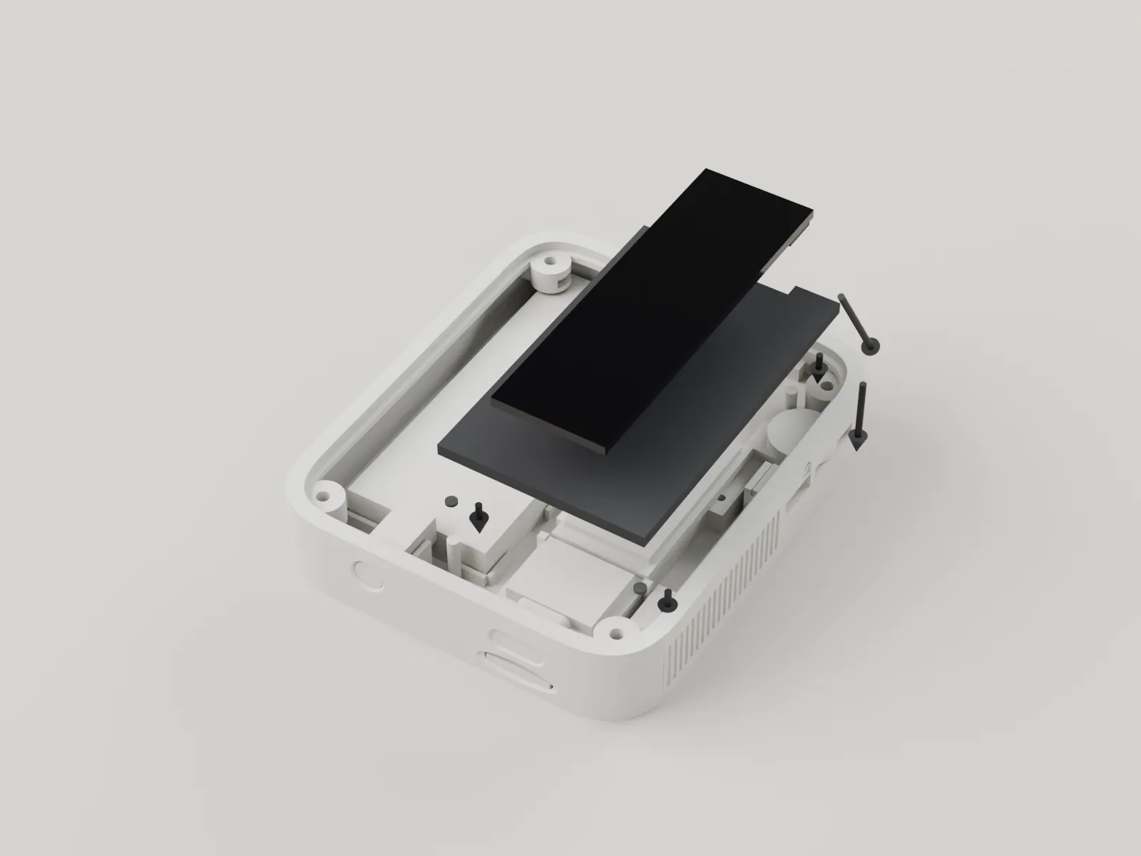
Colour module: Stick a 0.5 foam pad on each of the four posts. Lay the module on the posts with its screen up and its connector tail toward the port end, with the module board over the posts.
Bar screens: Stick a 0.5 foam pad on each of the four posts. Tape the flex adapter board to the back of the glass, plug the flex into it, and wrap the flex round the end of the carrier through the 18 wide relief in the top end shelf. Seat the screen carrier on the posts, the glass on top of it, the adapter through the carrier window.
Wire the module as section 06 says before it goes down, with its wires leaving at the tail.
The module (or the glass) lies level on the four pads, about 0.2 under the QT Py's tallest part. The pads press it up into the band in the next step, so it must rock freely before then.
-
08
Put the key caps into the deck
Deck, 4 key caps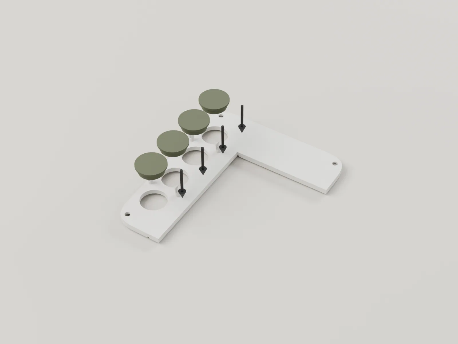
Turn the deck over, face down on the cloth. Drop each round cap into its hole from the underside, flange first, stem toward you. The flange holds the cap in the deck, and the cap should move freely by about a quarter millimetre.
All four caps drop in without force, spin freely and stand about 0.8 above the deck's face when you turn it over.
-
09
Snap the key carrier on
Key carrier, 4 tact switches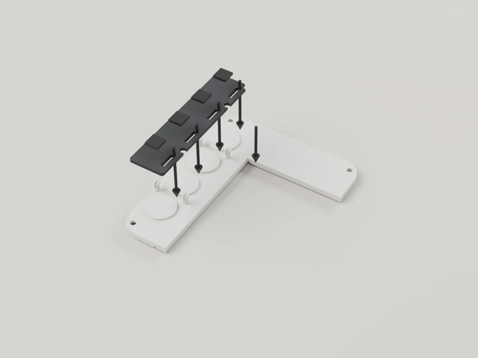
Seat a tact switch in each of the four fenced pockets of the carrier, then wire them (section 06) through the slots in the carrier's edge. Press the carrier onto the four split posts under the deck until each barb clicks. The carrier's corner is notched so it clears the jack's tail.
The carrier is level and does not rock. Press each cap: you feel a click at about a quarter millimetre of travel, and the cap springs back.
-
10
Lay the band over the screen
Band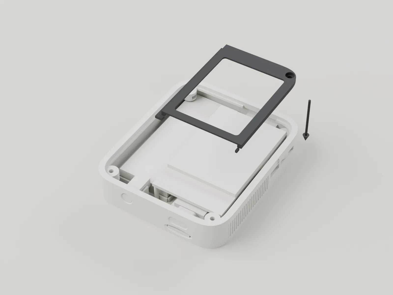
Lay the band over the screen with its window over the glass, its flange down in the shelf at the left edge. The glass sits in the pocket under the band's 0.8 lip. The band's top right corner has a column for the fourth screw.
The band lies flat on the shelf with its edge 0.4 below the rim, and the glass shows through its window with no gap at the lip.
-
11
Lower the deck
Deck, key caps, key carrier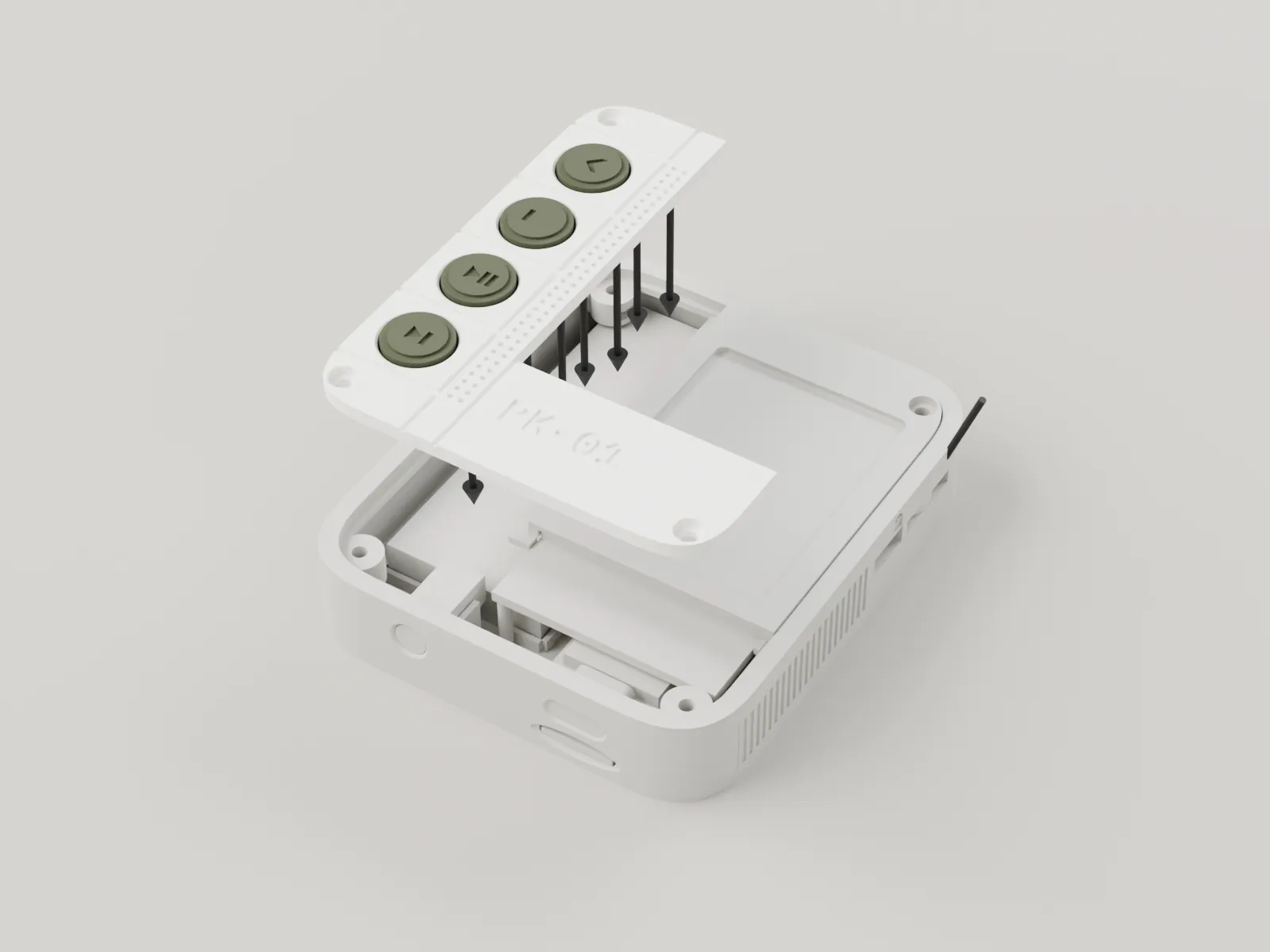
Plug the key ladder wires in place if you have not yet (section 06). Connect the cell last: the cell lead to the charger module and the QT Py's BAT pads, with the right polarity. Lower the deck onto the shell with the carrier over the cell, tucking the wires in. The band and the deck close with a 0.8 seam.
The deck lies flat with no wire under its edge, and the four screw holes line up with the nuts below.
-
12
Fit the four screws
3 x M2 x 8 and 1 x M2 x 5 button head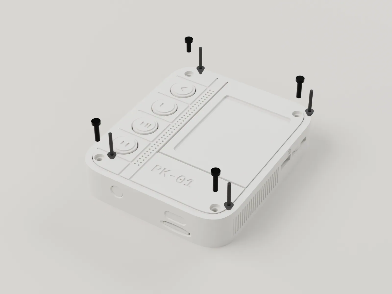
Put an M2 x 8 button head screw in each of the three holes at the bottom left, bottom right and top right, and the shorter M2 x 5 in the top left hole, over the cell. Tighten them with the 1.5 mm hex key, a little at a time, in a cross pattern. The top right screw passes through the band. Stop when the heads sit flush.
All four heads are flush with the deck. The tip of each screw stops in its nut, short of the cell and the boards.
-
13
Fit the wheel sleeve and the hold cap
Wheel sleeve, hold cap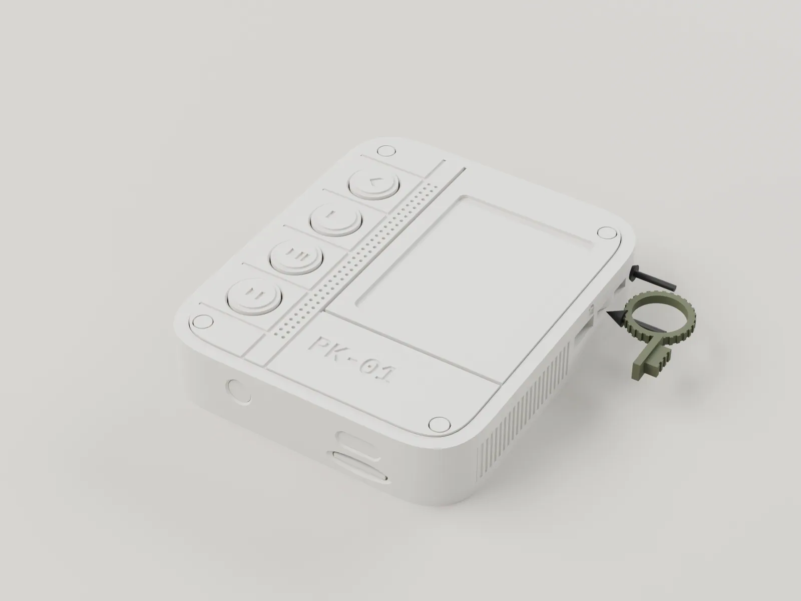
Press the wheel sleeve onto the encoder dial through the slot in the right wall, evenly, until it stands 1.4 proud of the edge. Press the hold cap onto the switch actuator through its slot in the right wall, below the wheel.
If either is tight, check the dial and the actuator against section 04. Never hammer.
The sleeve turns the dial and clicks when you push it. The hold cap slides about 1.5 mm each way, and the switch moves with it.
-
14
Load a record card, or the blank
Record card or slot blank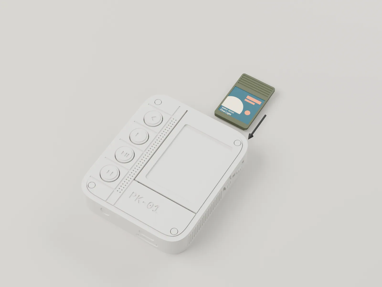
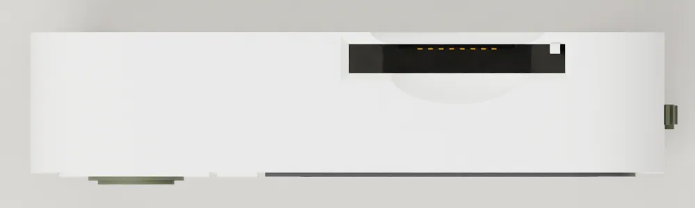
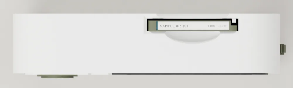
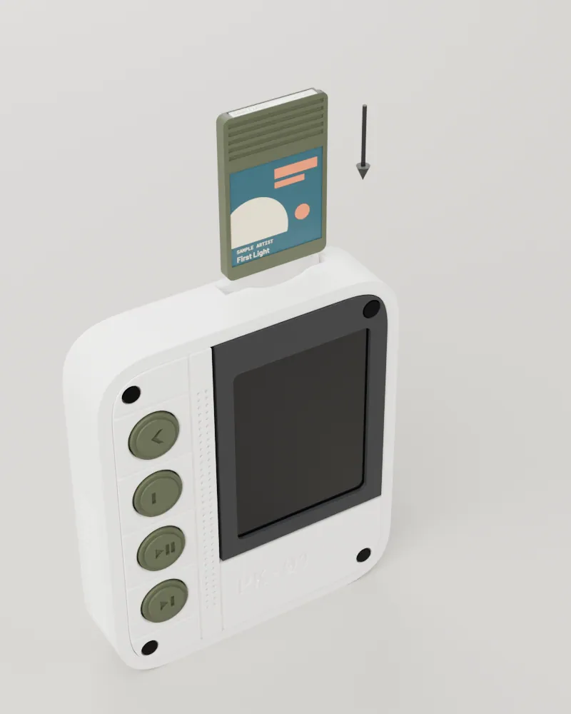
Hold the card with its label toward the screen and its ribbed end toward you. Line up the other end, the one with the eight gold pads on its underside, with the slot in the top edge, and push the card straight in. A small rib in the channel runs in the cut along one edge of the card, so it only goes in one way round. The card stops against the printed shoulders, and its ribbed end finishes level with the top edge. There is no latch: the springs under the card and the roof above it hold it by friction.
To take a card out, press the ribbed end with a thumb in the scoop on the front of the end wall, put a fingertip in the notch in the back under it, pinch, and pull the card straight up.
Without the record card reader, press the slot blank in the same way instead: two small crush bumps on its sides hold it, and it closes the slot against dust.
The card goes the whole way with a light push and no force, stops, and sits level with the top edge with nothing standing out of it. Pulled out and pushed in a few times it feels the same each time.
Which screw goes where
only one kind| Screw | Where | Into |
|---|---|---|
| M2 x 8 ISO 7380 button head, black (3) | deck, at (7, 7), (59, 7) and (59, 71) measured from the port end left corner; the (59, 71) one through the band | an M2 nut in the side slot of each boss |
| M2 x 5 ISO 7380 button head, black (1) | deck, at (7, 71): the top left boss hangs over the cell | the M2 nut in the raised slot of that boss |
First power-up and using the player
Power it from USB first, with the deck still easy to lift, and look before you listen.
- Before the cell goes in, plug the QT Py into USB with no cell connected. The board should start and the screen should light.
- Connect the cell and unplug the cable. The player runs from the cell. Plug the cable in again: the charger module charges the cell from USB. Watch the cell for the first charge and stop at once if it warms.
- Check each control. Turn the wheel (volume on Now Playing, scroll elsewhere), push it (select), press each key, and slide the hold switch (it locks everything).
- Plug in in-ear monitors with the volume at its start level, and play a track from the library card.
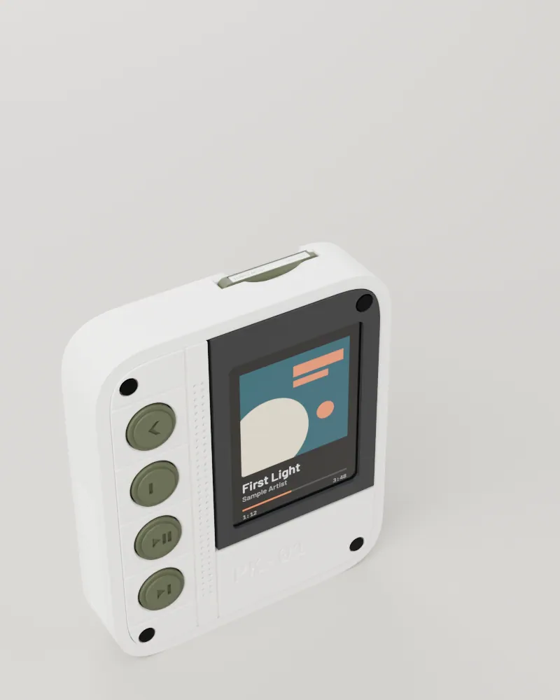
- Optional: try a record card. Push a card in as in step 14. The player should see it by itself once its pads touch the springs (section 10), mount it, and start playing its album from the first track. Taking the card out stops it and returns to the library.
Using it
controls| Control | What it does |
|---|---|
| Wheel, turn | volume on Now Playing; scrolls a list elsewhere (fast turns step letter by letter in a sorted list) |
| Wheel, push | select |
| Back | up one level; held, back to Now Playing |
| Prev, Next | press to skip; hold to scrub |
| Play | press to play or pause; hold 2 seconds to switch off |
| Hold slide | locks every control |
| Settings | volume limit, brightness (no effect with the backlight on 3V3), screen timeout, auto sleep, sort "The", output (jack or Bluetooth), rebuild library, Bluetooth (the device list), About. There is no USB storage mode on this board |
On the first boot with a library card the player builds an index in /.pk01/index.bin (the target is 5,000 tracks in under 3 minutes). Back stops it. To update the firmware, copy a new pk01.bin to the library card root and restart: the player offers it, and Play installs it.
Sound out
jack and BluetoothThe jack. The 3.5 mm jack is the DAC board's output and always works, whatever else is connected.
Bluetooth. The QT Py ESP32 Pico is a classic ESP32, so the player acts as a Bluetooth (A2DP) source and plays to wireless headphones and speakers. It sends audio only; it does not receive from a phone. To pair, put the headphones in pairing mode, then open Settings, Bluetooth: the list scans while it is on screen, strongest device first. Select yours: the player pairs, connects, remembers it and switches the output to Bluetooth. After that the player reconnects to the last device by itself whenever Bluetooth is the chosen output (it tries again for a few minutes if the headphones are off), and playback pauses while the link is down and resumes when it is back. Settings, Output switches between the jack and the remembered device. The audio is resampled to 44.1 kHz and sent as SBC by the stack, so a 24 bit / 96 kHz file loses its extra resolution on this path; the jack stays the bit-perfect output. Streaming costs battery, and decoding 24 bit / 96 kHz FLAC while sending Bluetooth audio has still to be proved on a built unit.
Record cards
A record card is a flat printed card that holds one album. It is 22 wide, 34 long and 2.6 thick, and nothing sticks out of it: a square label and a ribbed grip on the face, a narrow label on the spine, and eight gold pads set level into the underside at the other end. The slot in the player's top edge takes one card; the rack files five. Everything in this section is optional: a player without the reader plays from its library card.
Two kinds of card
same printed card, same padsmicroSD in a card: Print a label half and a contact half. A stock microSD sits in the window of the contact half with its own gold pads facing down, level with the card's underside, and is taped to the label half. It shows as a small black card with gold pads.
Card circuit board: Print the same two halves, but put a 0.4 mm board in the window instead of the microSD. The board is the microSD's outline, 11 x 15, with black solder mask and eight gold pads at 1.1 pitch on its underside. An SD NAND chip (6 x 8 x 0.75, LGA-8) is soldered on the other side, up inside the label half's pocket.
The printed card, the pads' places and the outside of the card are the same for both, so the one reader reads either. No bare green board shows anywhere on a card.
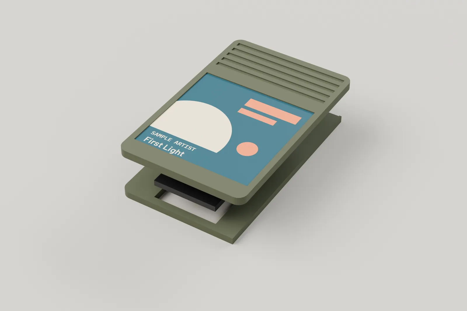
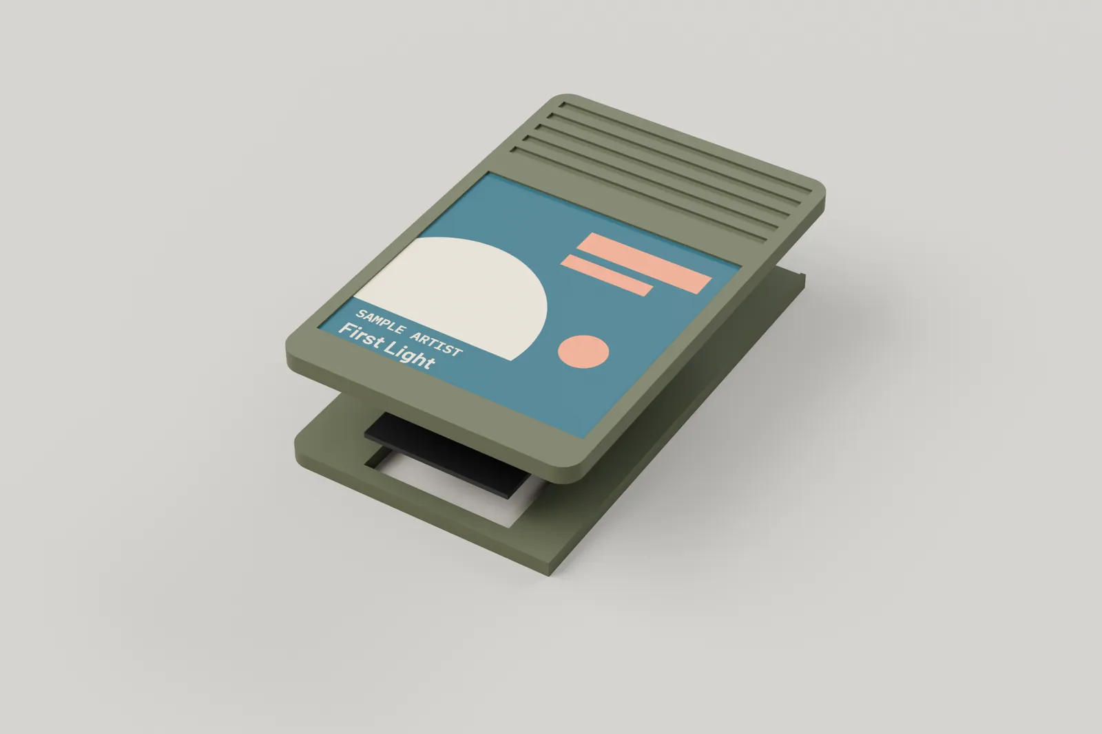
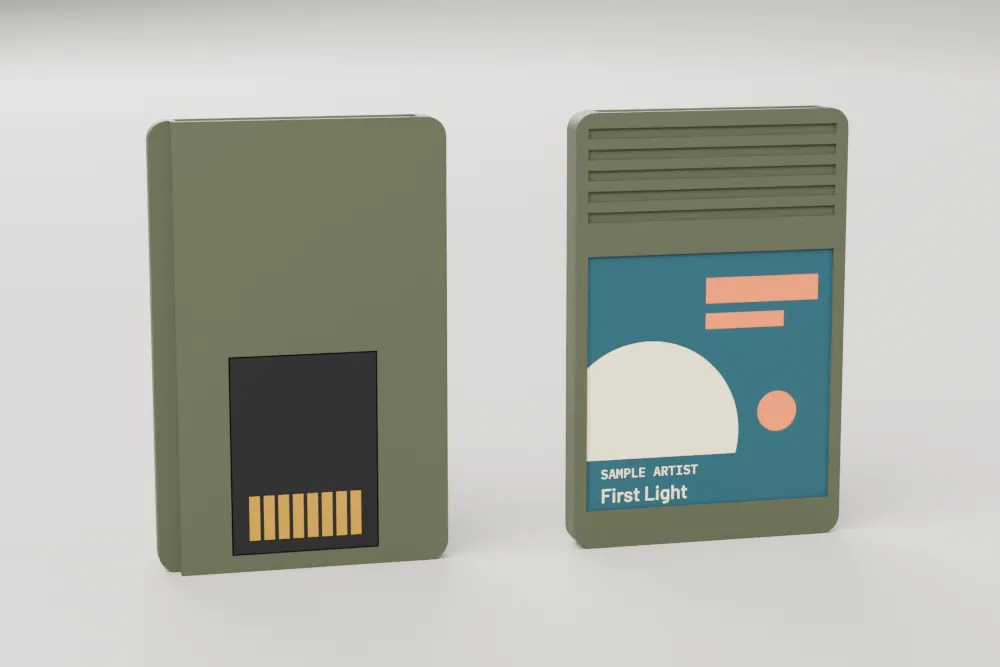
The label side faces the screen when the card is in. The underside faces the back of the player and carries the pads: they sit 0.05 inside the face, so a card lying on a desk never rests on them, and a card in the rack stands on its flat leading edge. A cut along one edge of the card is the key: a small rib in the slot runs in it, so a card turned over or round stops at the mouth.
How the slot reads a card
springs, stops and a key, no latchThe channel. A printed channel runs the full length of the card, 0.3 wider a side and 0.5 deeper than the card, with a 0.8 lead-in at the mouth. A 1.0 rib on its floor runs in the card's key cut.
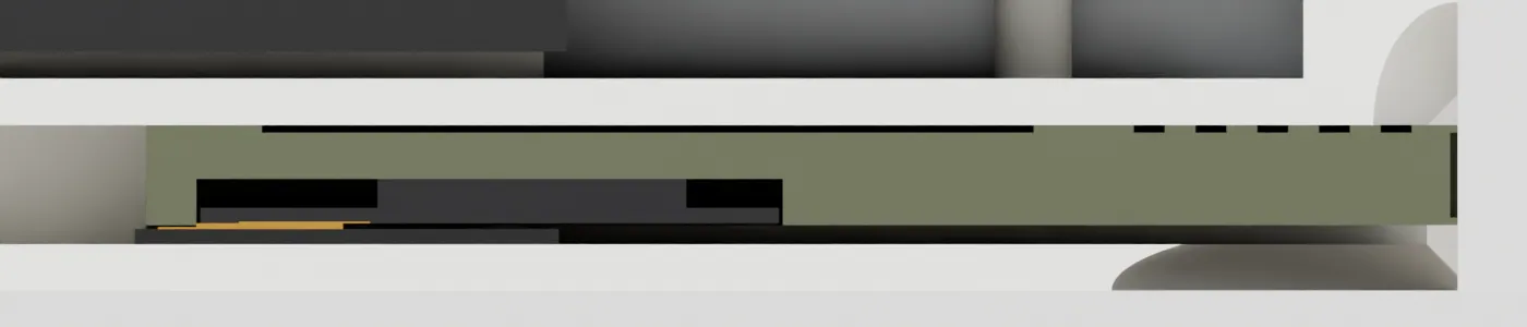
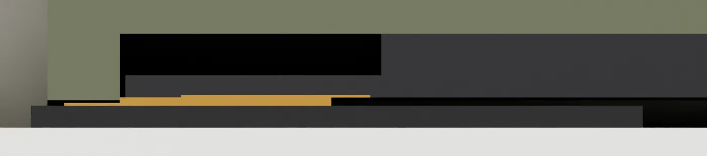
The springs. A strip of spring contacts lies flat on the channel floor under the card and presses on its gold pads. Its eight springs stand 0.35 proud of the base, touch the pads 1.7 from either end of each pad, and are pressed down 0.2 by the card, which leaves 0.15 before the base stops them. They push the card up against the channel roof, and friction holds it: there is no latch to wear.
The stops. Two printed shoulders stop the card's leading edge 0.3 before the reader's rear edge, so a card pushed hard loads the resin and not the springs. Its ribbed end then finishes level with the top edge.
Card detect. There is no switch. A seated card pulls its own chip select line (microSD pin 2, held up inside the card) high against a 1 M resistor to ground in the player. The player sees a card only when the pads really touch the springs. The firmware does this: every 150 ms, while no card is mounted, it lets go of the line, reads it, and takes three high readings in a row as an insert; it then mounts the card at /rec, scans it and plays its first album from the first track, showing Now Playing. While a card is mounted the line belongs to the card bus, so the firmware asks the card for its status instead, and two missed answers in a row count as removal: the album stops and the player returns to the library. After a removal, or a card it could not read, the line must be seen low once before another insert is accepted, so a card that is half out does not mount again and again. A card with more than one album plays the first. If the Premium board does not have its own 47 k pull-up on that line (check its datasheet), add one, or it will not be seen. This is written but has not run on a built player.
Putting a card in and taking it out
five movements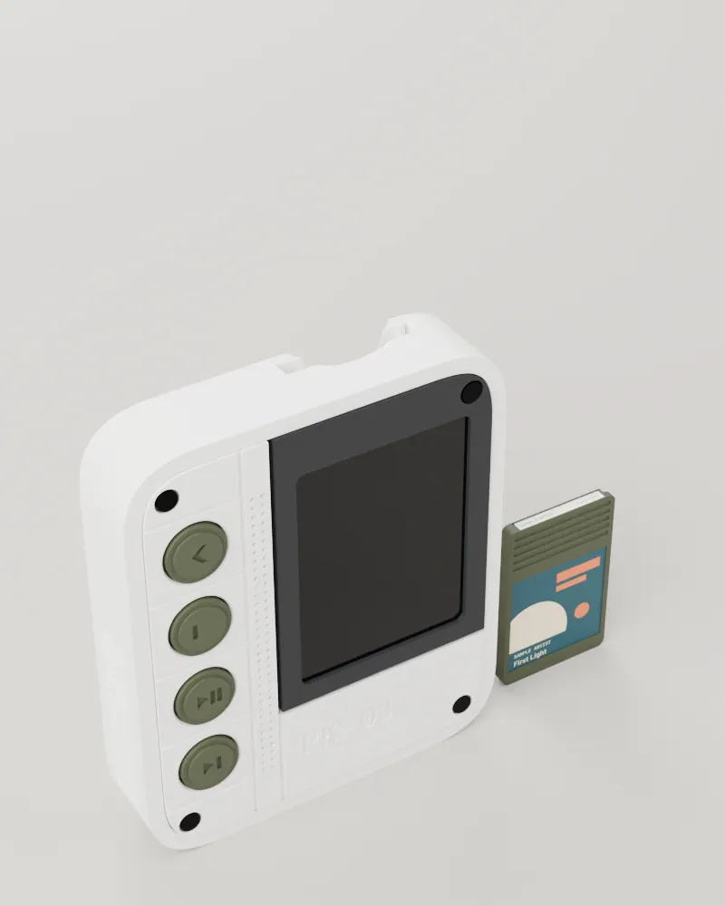
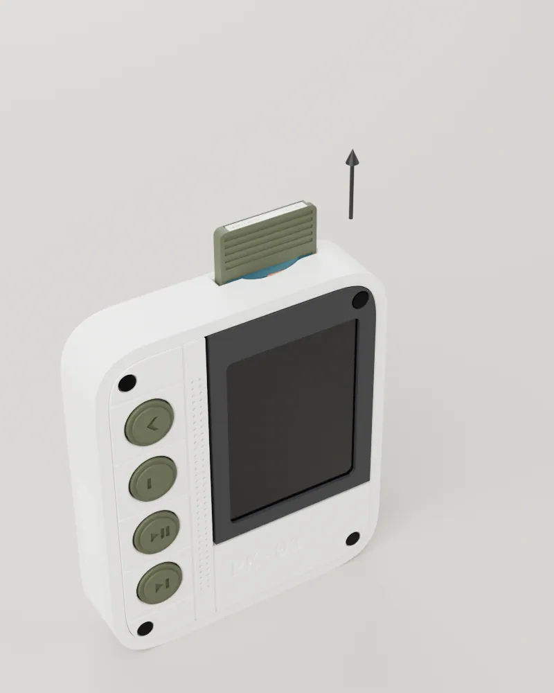
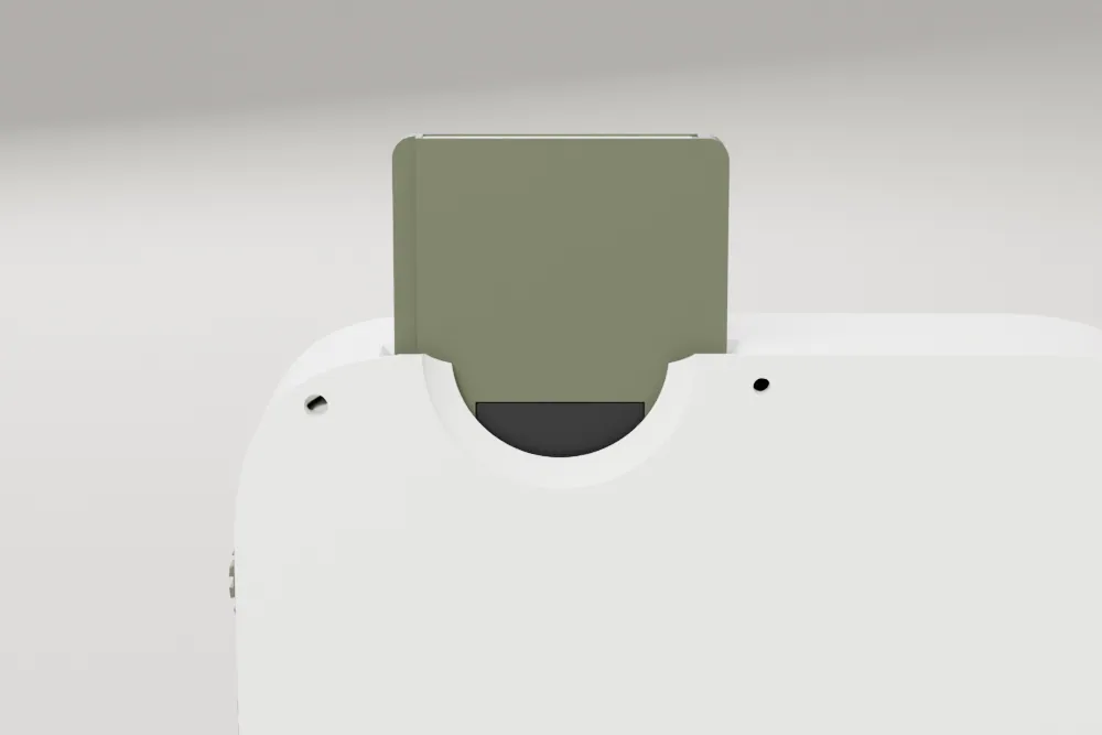
Pinch the ribbed end between a thumb in the scoop in the front of the end wall and a fingertip in the notch in the back skin, then pull the card straight up and out. The card never clicks or locks. Without the reader, the slot blank goes in and out the same way.
Printing and assembling a card
label half, contact half- Print the halves. The label half (
pk01_card_face.stl, label face up) and the contact half (pk01_card_frame.stl, contact face up) are in section 03. Supports go on the inner faces, which are joined together. Wash, cure and sand the support nubs flat, keeping the sanding off the pocket walls and the card's edges, which must stay 22.0 wide. - Paint the outside before you add the medium, one colour per card. Keep paint out of the window in the contact half and off the label recess, the spine recess and the key cut.
- microSD in a card: Fit the microSD. Put a 0.2 foam tape pad on the label half's inner face, set the microSD in the window with its pads facing out and its leading edge, the end with the pads, toward the card's leading end, and press it onto the tape. The tape also takes up the 0.2 between a 1.0 thick microSD and the 1.2 thick contact half.
- Card circuit board: Order and fit the board.
out/card/pk01_premium_card_pcb.dxfgives the outline, the eight pads and the chip area on separate layers, andpk01_premium_card_pcb.stepthe 0.4 board with the chip. Order 0.4 mm FR4 with black solder mask and ENIG gold on the pads, and route the chip to the eight pads from its datasheet: the pads follow the microSD pad order. Solder the chip on the side opposite the pads. If the chip has no pull-up on its chip select line, add a 47 k resistor from chip select to 3V3 on the board: the player's card detect depends on the card pulling that line high. Then tape the board to the label half like the microSD, pads out. - Close the card. Put a thin line of cyanoacrylate along the seam of the two halves, away from the window, press them together flat and hold until set.
The card is 22.0 wide, 34.0 long and 2.6 thick, give or take 0.1, and nothing stands out of any edge or face. The eight pads are level with the underside to within 0.1: lay a steel rule across the face and you should see no pad above it. The assembled board and chip must be no thicker than 1.15 behind the pad face. Slide the finished card into the slot: it must go in the whole way with a light push and stop with its end level with the edge.
Filling a card on a computer
folders, cover, album.jsonPlug the card into a computer and format it FAT32 (exFAT for a card over 32 GB). A record card is filled like the library card, and the player reads this layout:
/Music/Artist/Album/01 Title.flac
/Music/Artist/Album/02 Title.flac
/Music/Artist/Album/cover.jpg      # or folder.jpg: shown on the colour screens only
/config.txt # library card only, section 07- Folders. One folder per artist and one per album. FLAC and WAV up to 24 bit / 96 kHz play; other files are skipped. Put one album on a card for the neatest result: a card is a record.
- Cover. Put
cover.jpg(orfolder.jpg, or the.jpegforms) in the album folder, square, about 600 x 600, saved as a baseline JPEG (a progressive JPEG or a PNG is not read). Without a file, the player uses the picture embedded in the album's first FLAC track, if it is a JPEG. The player crops it to its centred square, shows it large on Now Playing and small beside each album in the lists, and keeps 160 and 64 pixel copies in/.pk01/arton the library card so the next time is instant; the first time an album is shown its cover appears a moment later, once decoded in the background. An album with no usable cover shows a plain dark tile with a note. A record card is never written to, so its cover is decoded each time. The OLED bar shows no art. - album.json. To be defined. The firmware does not read an
album.jsonfile yet and no format is fixed. The player takes album, artist and track names from the tags in the music files. Until the format is defined, keep no file of that name on a card, and keep your own notes elsewhere.
Printing and fitting labels
face and spineLabels are adhesive vinyl on sticker paper, printed at 600 dpi and cut to size. Both lie in recesses 0.2 deep so they sit flush; cut each about 0.1 under the recess size so it lies flat and cannot lift at an edge.
| Label | Size (mm) | Where it goes |
|---|---|---|
| Face | 20 x 20 | the square recess on the label half, 1.0 from each side and 11.0 from the ribbed end. Print the art upright for a card held label side up with the ribbed end at the top, as it sits in the player |
| Spine | 18 x 2.2 | the recess across the ribbed end, over both halves, 2.0 from each side. It reads along the spine, and shows when the card stands in the rack |
| Underside | none | the underside carries the window and the pads, so it has no label |
Paint and seal the card first, then peel each label and lay it on from one edge so no air is trapped. Press it flat with a soft cloth.
The rack
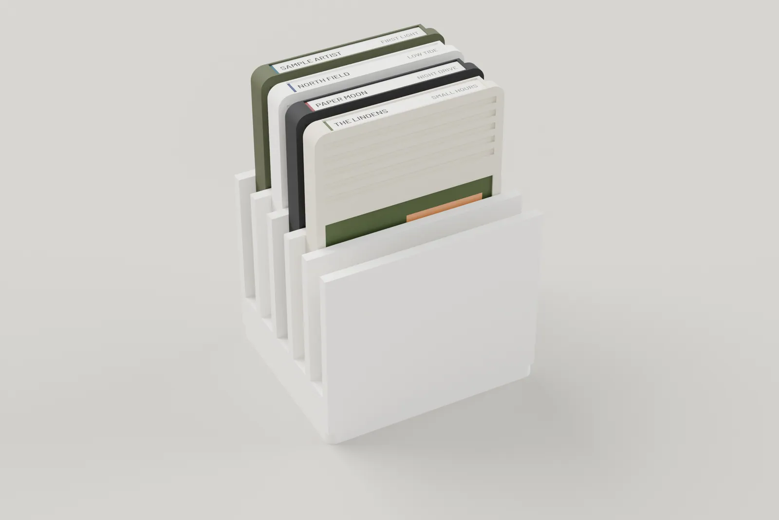
five cards, spines outThe card rack (pk01_card_rack.stl, printed once) holds five cards standing on their flat leading edge, spine up, so the spine labels read like records on a shelf. The pads are on the underside and never touch the rack's ribs or base. Each slot is 3.0 wide and has a drain slot under it. The rack is 22.2 x 25.8 x 22.
Docking in the SP-01 dock speaker
The SP-01 dock edition holds a PK-01 upright in a slot in its face. This section covers what the dock is specified to do with it.
- How it sits. The player stands upright, ports down, with its screen toward the listener, dropped in from the top. It stands about 36 mm proud of the speaker's top, so the wheel, the keys, the screen and the hold slide stay usable while it is docked.
- The slot stays clear. The record card slot is in the top edge, which faces up when the player is docked and stays clear, so you can swap cards while it plays.
- The fit. The dock's bay is built for this 66 wide body.
- Power. The dock's plug charges the player through its USB-C port, and tells it that it is docked: the player senses the supply on its battery and USB sense pin (section 06). There are no extra contacts on the port end.
- Music. Once docked, the player connects to the dock over Bluetooth by itself at close range and plays through the speaker automatically, with no pairing to do. When the supply on the sense pin rises above 2.35 V (three readings in a row), the player lets go of any headphones (one Bluetooth link at a time), then reconnects to the dock it has bonded with or, the first time, looks for a device named exactly
SP-01 dockand connects to the strongest one above -55 dBm, which is a dock within about a metre (a docked player is at about -28 dBm). The dock accepts a new bond only from a device namedPK-01above -45 dBm, so only a docked player can bond; later docks reconnect from the stored bond, within a few seconds. The audio switches to the dock once the link is up, and the music carries on from where it was. On a wall charger there is no dock to find: the player tries for about half a minute and then stays quiet until USB is unplugged and plugged in again. The dock never appears in the Settings list. This is written but has not run against a real dock: the range and timing are the first things to check. - Lifting it out. The slot is top loading: the player lifts straight out. When the supply drops the player lets go of the dock and goes back to the output it had before, the jack or the remembered Bluetooth headphones (which reconnect), without you choosing anything. A docked player does not switch itself off while paused.
Troubleshooting
| Symptom | Check |
|---|---|
| The board will not start or will not flash | the DAC data wire on the MI pad must read low at reset (no pull-up on the DAC input); the screen's DC wire on the BOOT pad must not be held low; hold BOOT, tap reset, then release BOOT to enter download mode |
| Nothing on the screen | 3V3 and GND at the module; the backlight pin is on 3V3; CS on A3, DC on the BOOT pad, DIN on MO, CLK on SCK; the pin header matches section 06 |
| No sound | DAC power and ground; BCK on SDA, LCK on RX, DIN on MI; the SCK pad grounded; tip and ring wired to the jack |
| Library card not found | card is formatted FAT32; CS on A2, CMD on MO, CLK on SCK, DAT0 on A0; the card is latched in its socket |
| Record card not seen | the card is pushed all the way in and level with the top edge; the springs are not bent and sit on the pads; CS (pin 2) goes to A1 with the 1 M resistor to GND; the eight wires go to the right tails; on a Premium card, the chip select pull-up is fitted |
| The card will not go in | it is turned over or round (the rib stops it at the mouth); a print burr in the channel; paint on the card's edges; a spring bent upward by a card pushed in sideways |
| The card falls out or rattles | springs too weak or a channel printed too wide; a 0.1 crush bump on a channel wall is the fix, never a latch |
| A key does nothing or two keys act together | the ladder resistor values; the node on the TX pad with its 22 k to 3V3; one side of every switch on GND |
| The deck will not sit flat | a wire under its edge, a cap stuck on its flange, or the screen module not rocking freely before the band is on |
| A cap sticks | paint in the hole or on the stem; thin the paint, not the cap |
| The wheel does not turn the encoder | the sleeve not fully on the dial; the dial rubbing the slot in the right wall; the A and B wires on the STEMMA lead (yellow and blue) |
| Cell will not charge | charger module IN+ on the 5V pad, OUT+ and OUT- to the cell and the BAT pads with the right polarity; the cell's protection board |
| Bluetooth range is short | a wire or the DAC's ground plane near the antenna end of the QT Py; move wires away from that end |
Licence and credits
| What | Licence |
|---|---|
| Firmware | MIT |
| CAD, print files, this manual and its images | © 2026 Rod Leviton, RPXL / Reactive Pixels. Licensed for building for your own personal use; not for redistribution or resale |
| Fonts embedded in this page: Inter, IBM Plex Mono. Font in the CAD: IBM Plex Mono | SIL Open Font License 1.1 |
| Firmware libraries: dr_flac, ESP-IDF, esp_tinyusb | their own licences |
© 2026 Rod Leviton, RPXL / Reactive Pixels. The PK-01 page and the rest of the range: B-Side. More from the studio at reactivepixels.com.