SP-01Speaker
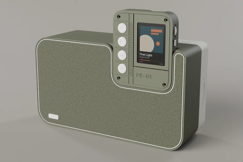
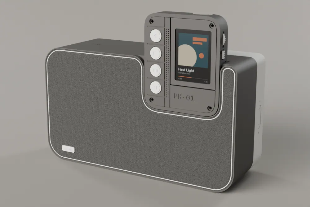
A Bluetooth speaker you build yourself. It is printed in resin, painted flat matte, with a stretched fabric face held at its edge by a white silicone cord rolled into a groove like a fly screen spline, and no glue. It plays from any phone over Bluetooth, with no app. The rocker on the end sets the volume, plays and pauses, and switches it on and off. It comes as a pocket speaker with a cell, and as a dock speaker that charges a PK-01 in a slot in its face and plays its music.
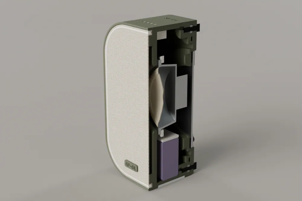
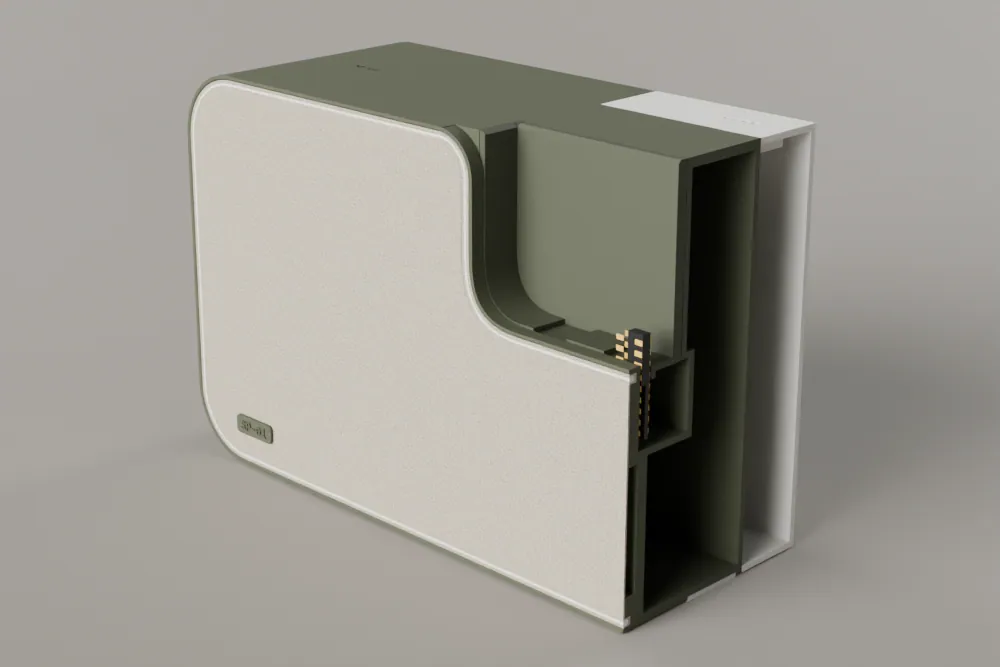
Every bought part is modelled at its nominal size, from its datasheet or listing. Measure each part when it arrives and compare it with the size in the parts list. A part more than 0.3 mm off is a change to params.py, after which print_files.py and the tests rebuild the files. The pictures are renders of the CAD model.
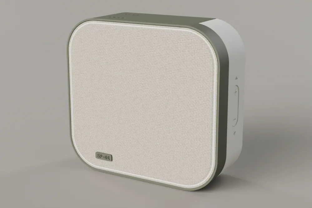
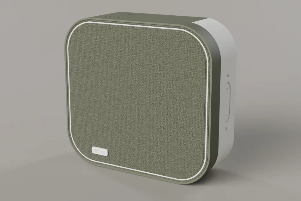
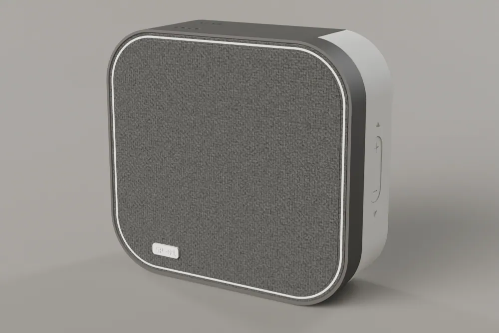
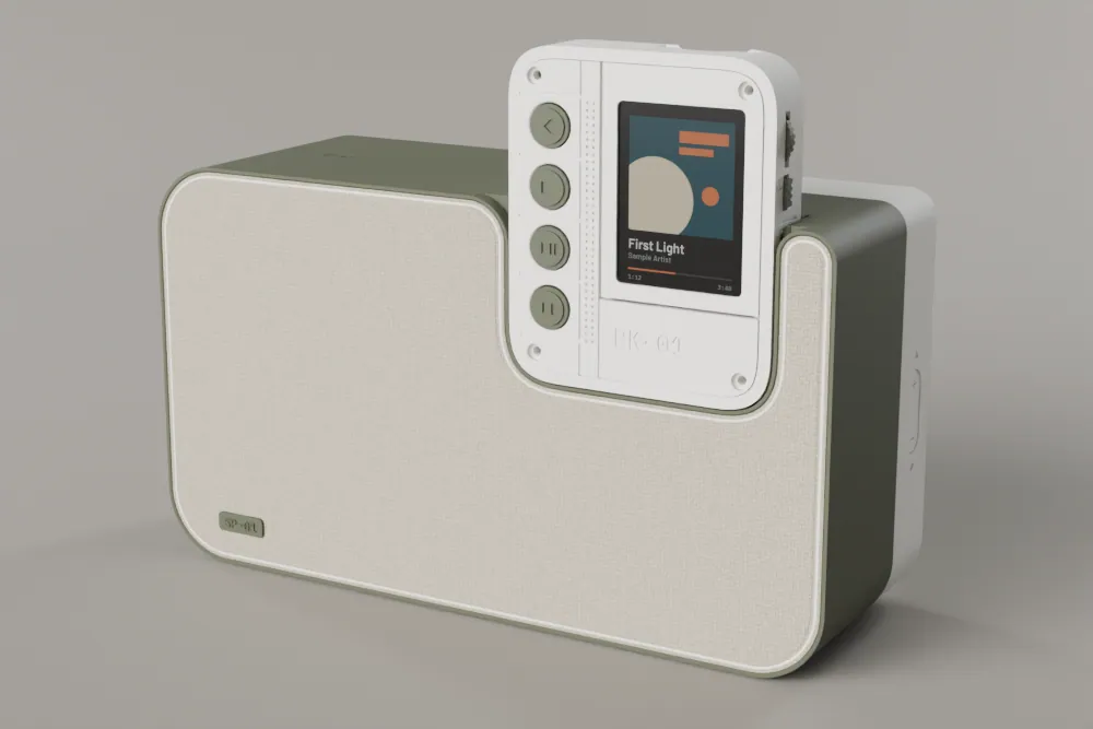
- Size
- 86 x 3080 mm high
- Size
- 185 x 62104 mm high, PK-01 36 more
- Sound
- 1 driver40 mm, with a passive radiator
- Sound
- 2 drivers45 mm, stereo, one radiator
- Power
- 1 cellUSB-C charging, about 5 h
- Power
- USB-C 5 V3 A, no battery
- Link
- BluetoothSBC, no app
- Controls
- 1 rockervolume, play, power, pairing
- Dock
- PK-01charges and plays, 36 mm proud
Choose your build
Two choices. The edition sets the size, the parts and the steps. The colourway sets the paint and the cloth only: every model and every print file is the same in every colourway. The rest of this page then shows your build only.
Choose a colourway
Paint and cloth onlyColourway
The cord is stock white silicone on every colourway, and the end block and rocker are painted to match it. Match the white paint against the bought cord.What you're building
A printed band with a fabric face, one 40 mm driver and a passive radiator, one cell, and a printed rack in a white end block that carries five bought modules, the rocker and the USB-C. A back plate carries the radiator and closes the band on a cord seal. Printed on a home MSLA printer, painted flat matte, and assembled with M2 screws and nuts.
A printed band with a fabric face, two 45 mm drivers side by side in one sealed chamber, and a passive radiator on the back plate. A channel in the face holds PK-01 on a dock plug that charges it, and a white end block carries the rocker, the USB-C input and a rack of bought modules. PK-01 stands 36 mm proud, and its wheel, keys, screen and hold slide are all usable. Its music plays through the speaker over Bluetooth.
How it works
Six ideasThe band is one print. The wrapping band, the crisp face rim, the fabric face border, the baffle that carries the drivers and the inner walls that make the chamber are one part, so the cord groove is one printed feature. It is open at the back, where the back plate closes it.
The face is cloth held by a cord. A white silicone cord, 1.6 round, rolls into a 2.2 wide groove round the edge of the face and pulls the cloth taut as it goes in. There is no glue, and the cloth can be replaced.
A sealed chamber. The chamber is sealed by the one piece band and the back plate on a cord seal, and every back screw is outside the seal. A passive radiator on the back plate tunes the box.
One sealed chamber. Both drivers share one chamber, sealed by the one piece band and the back plate on a cord seal, and every back screw is outside the seal. A 50 x 90 passive radiator on the back plate tunes the box. The plug bay is inside the chamber.
One rocker. Up and down is the volume, a centre press plays or pauses, a 2 second hold switches on or off and a 6 second hold starts pairing.
Bought modules, soldered wire. The controller, amplifier, booster, charger and the three switches slide into a printed rack, and you join them with 28 AWG wire: no custom board, no crimping.
Bought modules, soldered wire. The controller, two amplifiers, the input breakout and the three switches sit on a printed rack, and you join them and the plug breakout with 28 AWG wire: no custom board, no crimping. The plug carries power only: PK-01's music goes over Bluetooth.
No inserts. Screws go into captive M2 nuts in printed traps, or into a tapped hole.
The lights
Four, on the top| From the left | Steady | Slow pulse | |
|---|---|---|---|
| 1 Power (battery) | on | battery under 15 % | not used |
| 2 Bluetooth | a phone connected | pairing mode, or reconnecting | |
| 3 Link | PK-01 streaming | pairing with PK-01 | |
| 4 ChargeDock power | charging | charge fault | the plug is live |
No AAC, aptX or LDAC (the Bluetooth stack decodes SBC only). No deep bass from the pocket speaker. No water resistance: the fabric face rules it out. No music over the dock plug: it carries power only, and PK-01's music goes over Bluetooth.
Tools and supplies
What you need besides the parts in section 03. Gather it before you start, so nothing is missing mid-step.
| Item | What it is for |
|---|---|
| Printing | |
| An MSLA resin printer with a build area of at least 196 x 122 mm and 210 mm of height, and a washing and curing station | Every printed part (or use a print service) |
| A slicer where you place the supports by hand | Every part is tilted and needs supports on named hidden faces (section 04) |
| IPA or resin cleaner, nitrile gloves, eye protection, ventilation | Washing parts; uncured resin |
| Finishing | |
| Flush cutters, a hobby knife, needle files | Support nubs (on hidden faces only), fit faces, the fibre holes |
| Wet and dry paper, 400 and 800 grit, and fine paper of 1000 grit or finer | Between primer and paint; polishing the ends of the light fibres |
| Pin vise and drill bits, 1.1 to 2.4 | Clearing the fibre holes (1.8) and the screw holes by hand |
| Masking tape and masking putty, and toothpicks | Keeping paint out of the nut traps, the holes and the gland groove; a toothpick in each fibre hole |
| Assembly | |
| 1.5 mm hex key, and a straight 1.5 mm hex driver with a shaft up to 3 mm | All M2 socket cap screws (the end block screws are driven straight along y) |
| Tweezers | Nuts, foam pads and the small parts |
| A soft cloth or foam sheet | Working on the face without marking it |
| Digital callipers | Measuring the cell, the cord, the cloth and the sheet before you start |
| A fly screen spline roller with a narrow fork (concave wheel) | Rolling the cord into the groove |
| A sharp snap-off knife with a fresh blade, and small sharp scissors | Trimming the cloth; cutting the blank and the feet |
| A cocktail stick or a small spatula | Sealant, UV resin and the thin film under the feet |
| A UV torch | Curing the resin round each fibre and each drain pin |
| Side cutters | Trimming fibres, drain pins and wire ends |
| Electrical | |
| A soldering iron with a fine tip, thin solder and flux, heat shrink and wire strippers | Every wire in the speaker (soldered to module pads and legs, no crimping) |
| A multimeter | Driver resistance, continuity and the first power-up |
| A USB-C cable and a computer with ESP-IDF 5.5 (see firmware/README.md) | Flashing the controller over its own USB-C |
| A USB-C 5 V 3 A (15 W) supply | Running the dock speaker; the input does not negotiate a higher voltage |
| A safe place for the LiPo cell: no piercing, bending or shorting its leads | A damaged or shorted cell can overheat |
Parts to buy
Choose a set of components (Budget, Mid or Premium) and order the long-lead driver early: the PUI driver has a long maker lead time. Any part matching the spec works. Prices are AUD estimates, not quotes.
Choose a set of components (Budget, Mid or Premium); all three use the same drivers and radiator and sound the same. Any part matching the spec works. Prices are AUD estimates, not quotes.
Every bought part is modelled at its nominal size, from its datasheet or listing. Measure each part when it arrives and compare it with the size in the parts list. A part more than 0.3 mm off is a change to params.py, after which print_files.py and the tests rebuild the files.
Parts by use
follows your edition| Part | Qty | Source | Spec | Fallback | Checked (2026-11-16) |
|---|---|---|---|---|---|
| Band | 1 | printed (your printer or a print service) | One print: band, face border, baffle and inner walls | printed, no stock to check | not applicable |
| Back plate | 1 | printed (your printer or a print service) | 2.4 thick, closes the band and carries the radiator | printed, no stock to check | not applicable |
| End block | 1 | printed (your printer or a print service) | White shell round the rear right corner, with the rocker opening and the input port | printed, no stock to check | not applicable |
| Rocker | 1 | printed (your printer or a print service) | The volume, play and power rocker | printed, no stock to check | not applicable |
| Light boot bar | 1 | printed (your printer or a print service) | Bonded under the top wall, with four fibre bores and four LED pockets; hidden | printed, no stock to check | not applicable |
| Module rack | 1 | printed (your printer or a print service) | Card slots for the bought modules and a seat for the three switches, inside the end block; hidden | printed, no stock to check | not applicable |
| Driver clamp ring | 1 | printed (your printer or a print service) | 1.6 thick; holds the 40 mm driver, which has no mounting ears; hidden | printed, no stock to check | not applicable |
| Battery strap | 1 | printed (your printer or a print service) | A printed bar across the cell; hidden | printed, no stock to check | not applicable |
| Clamp plate, end block pass-through | 1 | printed (your printer or a print service) | 1.2 plate over the lead slot in the notch wall; hidden | printed, no stock to check | not applicable |
| Drain pins | 1 | printed (your printer or a print service) | One print of pins on a runner; each is cut to its hole and glued in; hidden | printed, no stock to check | not applicable |
| Badge | 1 | printed (your printer) | Raised SP-01 letters and two printed pegs | printed, no stock to check | not applicable |
| 40 mm full range driver | 1 | bought | Round, neodymium, 4 ohm; flange 40 across and 1.7 thick with no mounting holes, no deeper than 20.5. Mid and Premium: PUI Audio AS04004PR-R; Budget: a generic 40 mm 4 ohm 3 W driver. The PUI driver has a long maker lead time: order it early | NO CONFIRMED FALLBACK (design call). The Budget generic 40 mm 3 W driver was not stock checked | 2026-11-16: element14 AU AS04004PR-R in stock, 173 (UK stock, 3 to 5 business days), A$13.63 inc GST (product page read). Maker lead time 20 weeks if element14 sells out |
| Passive radiator, 50 round | 1 | bought | Rubber surround, adjustable mass, 50 mm; Mid and Premium: a 50 mm class radiator, Budget: a plain 50 mm round | NO CONFIRMED FALLBACK (design call). Dayton DMA58-PR at salinapp.com.au was seen in a search snippet only; no 50 mm radiator found at Core, Little Bird or Altronics | not stock checked, 2026-11-16: AliExpress listings only, no AU stock found. The 50 x 90 racetrack has guessed T/S: measure first |
| LiPo cell, 102050 | 1 | bought | 1 cell, 10 x 20 x 50 mm (the bay takes 10.5 x 20.5 x 50.4), about 1000 mAh, with a protection board and a JST PH 2.0 plug. Ask the seller about shipping lithium cells to Australia | Not checked at an AU source; no 102050 cell found at Little Bird or Core. NO CONFIRMED FALLBACK (design call: the bay is 10.5 x 20.5 x 50.4) | not stock checked, 2026-11-16: no AU listing found |
| Controller board, QT Py ESP32 Pico | 1 | bought | Adafruit ADA5395, 22.0 x 17.9 x 5.9 mm, classic ESP32 with USB-C; held in the rack by its two short edges, antenna end up | Little Bird AF-5395, A$31.55, 28 at supplier (catalogue page read) | 2026-11-16: Core Electronics in stock, A$28.30 (search page read). Little Bird in stock, A$31.55 |
| I2S amplifier board, MAX98357A | 1 | bought | 19.4 x 17.8 mm with the pins on one short edge; the slot takes no longer a board. Budget and Mid: a clone; Premium: Adafruit 3006. The dock takes one a channel | DFRobot DFR0954 module: Core A$9.84 and Little Bird A$9.24 in stock (search pages read). Board size not confirmed, the slot takes at most 19.4 x 17.8 mm, so measure first; SparkFun SF-DEV-14809 (Little Bird A$15.20) is larger | 2026-11-16: Core Electronics Adafruit 3006 in stock, A$10.65 (search page read). Little Bird and Adafruit: out of stock |
| 5 V booster board, MiniBoost 5V 1A | 1 | bought | Adafruit ADA4654, 17.8 x 11.3 x 5.6 mm; feeds the amp only | No second booster checked; the Adafruit 3661 (100 mA) is too weak for the amp | 2026-11-16: Core Electronics in stock, A$7.65. Little Bird in stock, A$8.15, 100 at supplier |
| USB-C Li-ion charger module | 1 | bought | About 10 x 7.5 x 5.2 mm, 600 mA; its USB-C socket is the outside port | none recorded | not individually checked, 2026-11-16 |
| Tact switch, 6 x 6 mm through hole | 3 | bought | 5.0 tall; two of 160 gf (the ends) and one of 260 gf (the centre) | Core Electronics tact switch packs (not opened) | 2026-11-16: Little Bird LB-LS6214 6 x 6 x 5 mm, 10 pack, A$1.10, 47 in Sydney |
| Pre-wired 0603 warm white micro LED | 4 | bought | 1.6 x 0.8 x 0.6 mm on enamelled leads; one per light | none recorded | not individually checked, 2026-11-16 |
| Resistors, 1/8 W | 1 | bought | Four 1 k, one in series with each LED; two 1 M (cell voltage divider); two 100 k (charger input divider) | none recorded | not individually checked, 2026-11-16 |
| STEMMA QT / Qwiic to bare wire lead, JST SH 4-pin | 1 | bought | Plugs into the controller's STEMMA QT socket: it carries GPIO 22 and 19, 3.3 V and ground | Little Bird has the 150, 200, 300 and 400 mm leads too | 2026-11-16: Little Bird AF-4399 STEMMA QT cable, A$2.15, 16 in Sydney |
| JST PH 2-pin socket lead, pre-crimped | 1 | bought | Mates with the cell's plug, so the cell can be unplugged; soldered to the charger's battery pads | Little Bird AF-3814 JST PH cable, A$1.65, 100 at supplier | 2026-11-16: Little Bird AF-4714 JST PH jumper 100 mm, A$2.10, 100 at supplier |
| Hookup wire, 28 AWG silicone | 1 | bought | Two or more colours: every wire between the modules, the drivers, the cell and the lights; they cross the lead slot in bundles. The CAD shows the cell, driver, light and dock wires | Core Electronics 22 AWG hookup kit, A$29.70 (thicker than spec) | 2026-11-16: Little Bird LB-PT-26AWG 5 colour silicone wire box, A$39.10, 25 in Sydney (28 AWG not found) |
| Screw, M2 x 8 socket cap | 6 | bought | DIN 912, A2 stainless, black; back plate into the rear lip nuts | none recorded | not individually checked, 2026-11-16 |
| Nut, M2 hex | 6 | bought | DIN 934, 4.0 across flats, 1.6 thick; in the rear lip traps | none recorded | not individually checked, 2026-11-16 |
| Screw, M2 x 6 socket cap | 2 | bought | DIN 912; end block to the ear nuts | none recorded | not individually checked, 2026-11-16 |
| Nut, M2 hex | 2 | bought | DIN 934; in the two ear traps of the notch wall | none recorded | not individually checked, 2026-11-16 |
| Screw, M2 x 4 socket cap | 4 | bought | DIN 912; driver or clamp ring into the blind nut traps | none recorded | not individually checked, 2026-11-16 |
| Nut, M2 hex | 4 | bought | DIN 934; in the blind traps behind the baffle | none recorded | not individually checked, 2026-11-16 |
| Screw, M2 x 5 socket cap | 4 | bought | DIN 912; radiator into the back plate posts | none recorded | not individually checked, 2026-11-16 |
| Nut, M2 hex | 4 | bought | DIN 934; in the traps of the back plate posts | none recorded | not individually checked, 2026-11-16 |
| Screw, M2 x 4 socket cap | 2 | bought | DIN 912; battery strap into the two posts | none recorded | not individually checked, 2026-11-16 |
| Foam gasket tape | 0.6 m | bought | Closed cell EPDM or PE, 3.0 x 1.5 mm, self adhesive; squeezed to 0.9 under drivers and radiators | none recorded | not individually checked, 2026-11-16 |
| Silicone cord, 1.6 white | 0.7 m | bought | Solid round, 60 Shore A, white (RS PRO 2325746, 10 m; the 1.5 mm RS PRO 2325745 also works). Stock cord only: it is never cast. The face loop (287 pocket, 605 dock) and the back seal (about 270 pocket, 390 dock), with spare | none recorded | not individually checked, 2026-11-16 |
| Grille cloth | 1 | bought | Knitted, stretchy, acoustically transparent polyester, solution dyed, about 0.5 thick; a blank of the face outline plus 8 all round (about 102 x 96 pocket, 201 x 120 dock). Oat, heathered olive or heathered charcoal | none recorded | not individually checked, 2026-11-16 |
| Clear silicone sheet, 1.0 or 1.2 | 1 | bought | Translucent, for the feet: pills 44 x 17.6 (one on the pocket, three on the dock). The recess follows the sheet you buy | none recorded | not individually checked, 2026-11-16 |
| End-glow fibre, PMMA | 4 | bought | 1.5 diameter (2.0 does not clear the 2.6 pitch), cut to length with both ends square; the pocket's are 4.8 long, the dock's 4.0 | none recorded | not individually checked, 2026-11-16 |
| Neutral cure silicone sealant | 1 | bought | Clear, for the pass-throughs; also a thin film under the feet | none recorded | not individually checked, 2026-11-16 |
| UV cure resin | 1 | bought | A small bottle, to glue the drain pins and fix each light fibre in its hole | none recorded | not individually checked, 2026-11-16 |
| Masking tape | 1 | bought | Low tack; holds nuts in their traps and the cloth in place | none recorded | not individually checked, 2026-11-16 |
| Grey filler primer | 1 | bought | Spray | none recorded | not individually checked, 2026-11-16 |
| Flat matte paint, body colour | 1 | bought | Olive near RAL 6003 (oat and olive) or graphite near RAL 7022; one colour for the band and the back plate | none recorded | not individually checked, 2026-11-16 |
| Flat matte paint, white | 1 | bought | Near RAL 9016 traffic white, matched against the bought cord; end block and rocker | none recorded | not individually checked, 2026-11-16 |
| Flat matte paint, badge colour | 1 | bought | One colour: olive on oat, white on olive and graphite (a small pot) | none recorded | not individually checked, 2026-11-16 |
| Part | Qty | Source | Spec | Fallback | Checked (2026-11-16) |
|---|---|---|---|---|---|
| Band | 1 | printed (your printer or a print service) | One print: band, face border, baffle and inner walls | printed, no stock to check | not applicable |
| Back plate | 1 | printed (your printer or a print service) | 2.4 thick, closes the band and carries the radiator | printed, no stock to check | not applicable |
| End block | 1 | printed (your printer or a print service) | White shell round the rear right corner, with the rocker opening and the input port | printed, no stock to check | not applicable |
| Rocker | 1 | printed (your printer or a print service) | The volume, play and power rocker | printed, no stock to check | not applicable |
| Channel cup | 1 | printed (your printer or a print service) | The liner that holds PK-01 and carries the dock plug breakout | printed, no stock to check | not applicable |
| Light boot bar | 1 | printed (your printer or a print service) | Bonded under the top wall, with four fibre bores and four LED pockets; hidden | printed, no stock to check | not applicable |
| Module rack | 1 | printed (your printer or a print service) | Card slots for the bought modules and a seat for the three switches, inside the end block; hidden | printed, no stock to check | not applicable |
| Clamp plate, end block pass-through | 1 | printed (your printer or a print service) | 1.2 plate over the lead slot in the notch wall; hidden | printed, no stock to check | not applicable |
| Clamp plate, plug bay pass-through | 1 | printed (your printer or a print service) | Over the dock lead slot in the plug bay wall; hidden | printed, no stock to check | not applicable |
| Drain pins | 1 | printed (your printer or a print service) | One print of pins on a runner; each is cut to its hole and glued in; hidden | printed, no stock to check | not applicable |
| Badge | 1 | printed (your printer) | Raised SP-01 letters and two printed pegs | printed, no stock to check | not applicable |
| 1.5 inch full range driver | 2 | bought | Dayton Audio DMA45-4, 4 ohm, 46 square flange; the baffle cutout is 38 and the screws sit on a 38 square pitch. Parts Express and Audiophonics ship to Australia | NO CONFIRMED FALLBACK (design call). No AU seller found | 2026-11-16: Parts Express 295-580 in stock, 102, US$8.98 (page read). Shipping to Australia not confirmed and no AU seller found. A$ price not known |
| Passive radiator, 50 x 90 racetrack | 1 | bought | Rubber surround, adjustable mass, supplied with its gasket frame | NO CONFIRMED FALLBACK (design call). Dayton DMA58-PR at salinapp.com.au was seen in a search snippet only; no 50 mm radiator found at Core, Little Bird or Altronics | not stock checked, 2026-11-16: AliExpress listings only, no AU stock found. The 50 x 90 racetrack has guessed T/S: measure first |
| Controller board, QT Py ESP32 Pico | 1 | bought | Adafruit ADA5395, 22.0 x 17.9 x 5.9 mm, classic ESP32 with USB-C; held in the rack by its two short edges, antenna end up | Little Bird AF-5395, A$31.55, 28 at supplier (catalogue page read) | 2026-11-16: Core Electronics in stock, A$28.30 (search page read). Little Bird in stock, A$31.55 |
| I2S amplifier board, MAX98357A | 2 | bought | 19.4 x 17.8 mm with the pins on one short edge; the slot takes no longer a board. Budget and Mid: a clone; Premium: Adafruit 3006. The dock takes one a channel | DFRobot DFR0954 module: Core A$9.84 and Little Bird A$9.24 in stock (search pages read). Board size not confirmed, the slot takes at most 19.4 x 17.8 mm, so measure first; SparkFun SF-DEV-14809 (Little Bird A$15.20) is larger | 2026-11-16: Core Electronics Adafruit 3006 in stock, A$10.65 (search page read). Little Bird and Adafruit: out of stock |
| USB-C 5 V input breakout | 1 | bought | 16 pin receptacle with 5.1 k on CC, 3 A rated, about 10 x 7.5; it is the outside port | Little Bird Adafruit 4090, A$6.45, 100 at supplier (catalogue page read) | 2026-11-16: Core Electronics Adafruit USB C breakout in stock, A$5.40 (search page read) |
| USB-C plug breakout | 1 | bought | Adafruit ADA5978, 24.1 x 14.3 x 3.1 mm: the dock plug that mates with PK-01 | Little Bird AF-5978, A$4.95, 100 at supplier (catalogue page read) | 2026-11-16: Core Electronics Adafruit 5978 in stock, A$5.45 (search page read) |
| Tact switch, 6 x 6 mm through hole | 3 | bought | 5.0 tall; two of 160 gf (the ends) and one of 260 gf (the centre) | Core Electronics tact switch packs (not opened) | 2026-11-16: Little Bird LB-LS6214 6 x 6 x 5 mm, 10 pack, A$1.10, 47 in Sydney |
| Pre-wired 0603 warm white micro LED | 4 | bought | 1.6 x 0.8 x 0.6 mm on enamelled leads; one per light | none recorded | not individually checked, 2026-11-16 |
| Resistors, 1/8 W | 1 | bought | Four 1 k, one in series with each LED; 10 k from 5 V to the plug's CC (Rp); 10 k and 270 k, the left and right amp's channel select | none recorded | not individually checked, 2026-11-16 |
| Resettable fuse (PTC), 1.1 A | 1 | bought | In the plug's VBUS wire; trips on a short in the channel | Not matched to 1.1 A | 2026-11-16: Little Bird SparkFun SF-COM-08357 PTC, A$3.55, 4 in Sydney (rating not confirmed as 1.1 A) |
| Electrolytic capacitor, 1000 uF 6.3 V | 1 | bought | Across the amps' 5 V supply | Little Bird TB-RE6316 1000 uF 16 V is out of stock | 2026-11-16: Little Bird SparkFun SF-COM-08982 1000 uF 25 V, A$1.15, 71 at supplier (larger body than a 6.3 V part, check the space) |
| STEMMA QT / Qwiic to bare wire lead, JST SH 4-pin | 1 | bought | Plugs into the controller's STEMMA QT socket: it carries GPIO 22 and 19, 3.3 V and ground | Little Bird has the 150, 200, 300 and 400 mm leads too | 2026-11-16: Little Bird AF-4399 STEMMA QT cable, A$2.15, 16 in Sydney |
| Hookup wire, 28 AWG silicone | 1 | bought | Two or more colours: every wire between the modules, the drivers, the cell and the lights; they cross the lead slot in bundles. The CAD shows the cell, driver, light and dock wires | Core Electronics 22 AWG hookup kit, A$29.70 (thicker than spec) | 2026-11-16: Little Bird LB-PT-26AWG 5 colour silicone wire box, A$39.10, 25 in Sydney (28 AWG not found) |
| Screw, M2 x 8 socket cap | 14 | bought | DIN 912, A2 stainless, black; back plate into the rear lip nuts | none recorded | not individually checked, 2026-11-16 |
| Nut, M2 hex | 14 | bought | DIN 934, 4.0 across flats, 1.6 thick; in the rear lip traps | none recorded | not individually checked, 2026-11-16 |
| Screw, M2 x 6 socket cap | 2 | bought | DIN 912; end block to the ear nuts | none recorded | not individually checked, 2026-11-16 |
| Nut, M2 hex | 2 | bought | DIN 934; in the two ear traps of the notch wall | none recorded | not individually checked, 2026-11-16 |
| Screw, M2 x 6 socket cap | 2 | bought | DIN 912; rack plate into the two tapped lugs of the end block | none recorded | not individually checked, 2026-11-16 |
| Screw, M2 x 4 socket cap | 8 | bought | DIN 912; driver or clamp ring into the blind nut traps | none recorded | not individually checked, 2026-11-16 |
| Nut, M2 hex | 8 | bought | DIN 934; in the blind traps behind the baffle | none recorded | not individually checked, 2026-11-16 |
| Screw, M2 x 5 socket cap | 4 | bought | DIN 912; radiator into the back plate posts | none recorded | not individually checked, 2026-11-16 |
| Nut, M2 hex | 4 | bought | DIN 934; in the traps of the back plate posts | none recorded | not individually checked, 2026-11-16 |
| Screw, M2 x 3 socket cap | 2 | bought | DIN 912; channel cup from the chamber side into its tapped holes | none recorded | not individually checked, 2026-11-16 |
| Foam gasket tape | 0.8 m | bought | Closed cell EPDM or PE, 3.0 x 1.5 mm, self adhesive; squeezed to 0.9 under drivers and radiators | none recorded | not individually checked, 2026-11-16 |
| Silicone cord, 1.6 white | 1.1 m | bought | Solid round, 60 Shore A, white (RS PRO 2325746, 10 m; the 1.5 mm RS PRO 2325745 also works). Stock cord only: it is never cast. The face loop (287 pocket, 605 dock) and the back seal (about 270 pocket, 390 dock), with spare | none recorded | not individually checked, 2026-11-16 |
| Grille cloth | 1 | bought | Knitted, stretchy, acoustically transparent polyester, solution dyed, about 0.5 thick; a blank of the face outline plus 8 all round (about 102 x 96 pocket, 201 x 120 dock). Oat, heathered olive or heathered charcoal | none recorded | not individually checked, 2026-11-16 |
| Clear silicone sheet, 1.0 or 1.2 | 1 | bought | Translucent, for the feet: pills 44 x 17.6 (one on the pocket, three on the dock). The recess follows the sheet you buy | none recorded | not individually checked, 2026-11-16 |
| End-glow fibre, PMMA | 4 | bought | 1.5 diameter (2.0 does not clear the 2.6 pitch), cut to length with both ends square; the pocket's are 4.8 long, the dock's 4.0 | none recorded | not individually checked, 2026-11-16 |
| Neutral cure silicone sealant | 1 | bought | Clear, for the pass-throughs; also a thin film under the feet | none recorded | not individually checked, 2026-11-16 |
| UV cure resin | 1 | bought | A small bottle, to glue the drain pins and fix each light fibre in its hole | none recorded | not individually checked, 2026-11-16 |
| Masking tape | 1 | bought | Low tack; holds nuts in their traps and the cloth in place | none recorded | not individually checked, 2026-11-16 |
| Grey filler primer | 1 | bought | Spray | none recorded | not individually checked, 2026-11-16 |
| Flat matte paint, body colour | 1 | bought | Olive near RAL 6003 (oat and olive) or graphite near RAL 7022; one colour for the band and the back plate | none recorded | not individually checked, 2026-11-16 |
| Flat matte paint, white | 1 | bought | Near RAL 9016 traffic white, matched against the bought cord; end block and rocker | none recorded | not individually checked, 2026-11-16 |
| Flat matte paint, face tone | 1 | bought | 434838 on olive bodies, 35332F on graphite; the channel cup only (a small pot or brush paint is enough) | none recorded | not individually checked, 2026-11-16 |
| Flat matte paint, badge colour | 1 | bought | One colour: olive on oat, white on olive and graphite (a small pot) | none recorded | not individually checked, 2026-11-16 |
| PK-01 pocket player | 1 | yours | Your own PK-01, with the firmware that supports the dock. Not part of this kit's cost | none recorded | not individually checked, 2026-11-16 |
What you buy, and what it costs
AUDPrices are AUD estimates on 30 October 2026, from list prices at Australian sellers and overseas sellers that ship to Australia. They are estimates, not quotes. Shipping, GST and import duty are in the shipping line, which is an estimate.
Budget, Mid and Premium change only the bought parts of the pocket: the driver, the radiator, the amplifier, the cell, the cloth, the foam, the fibre, the feet, the fasteners and the finish. The printed casing is the same in all three, and so is every part a fit depends on. Colour is a separate choice: any colourway goes with any set.
| Slot | Qty | Budget | Mid | Premium |
|---|---|---|---|---|
| Resin | 1 | Resin for the pocket print set (volume from the STL files) (AUD 3.35) | Same in all three | |
| Finish | 1 | Abrasives for the satin finish (800 grit and a scuff pad) (AUD 3.00) | Filler primer, one matte colour and white for the end block and rocker (AUD 37.00) | Filler primer, two colour coats and white, wet sanded between coats (AUD 53.00) |
| MCU | 1 | Adafruit QT Py ESP32 Pico (ADA5395) (AUD 31.55) | Same in all three | |
| Booster | 1 | Adafruit MiniBoost 5V 1A (ADA4654) (AUD 8.15) | Same in all three | |
| Charger | 1 | USB-C mini Li-ion charger module, 600 mA, about 10 x 7.5 mm (AUD 1.50) | Same in all three | |
| Switches | 3 | 6 x 6 mm through-hole tact switch, 5.0 tall (two 160 gf, one 260 gf) (AUD 2.00) | Same in all three | |
| LEDs | 4 | Pre-wired 0603 warm white micro LED on enamelled leads (4) (AUD 2.50) | Same in all three | |
| Resistors | 1 | Resistors, 1/8 W assortment (four 1 k for the LEDs, two 1 M and two 100 k for the sense dividers) (AUD 0.50) | Same in all three | |
| STEMMA QT lead | 1 | STEMMA QT / Qwiic to bare wire lead, JST SH 4-pin (AUD 1.50) | Same in all three | |
| PH socket lead | 1 | JST PH 2-pin socket lead, pre-crimped (mates with the cell's plug) (AUD 1.00) | Same in all three | |
| Hookup wire | 1 | 28 AWG silicone hookup wire, two colours (AUD 1.50) | Same in all three | |
| Amplifier | 1 | MAX98357A I2S amp breakout (clone, no longer than 19.4 mm: check on arrival) (AUD 3.35) | MAX98357A I2S amp breakout (clone, no longer than 19.4 mm: check on arrival) (AUD 3.35) | Adafruit MAX98357A I2S amp breakout (3006) (AUD 9.24) |
| Driver | 1 | Generic 40 mm 4 ohm 3 W driver (2 in the pack, flange 40, depth 20.5 at most) (AUD 1.98) | PUI Audio AS04004PR-R 40 mm driver (AUD 11.00) | PUI Audio AS04004PR-R 40 mm driver (AUD 11.00) |
| Radiator | 1 | Passive radiator 50 mm round (pack of 2) (AUD 1.69) | Passive radiator 50 mm class (pack of 2) (AUD 4.80) | Passive radiator 50 mm class (pack of 2) (AUD 4.80) |
| Cell | 1 | 102050 LiPo cell, 1000 mAh, with protection board and JST PH 2-pin (AUD 6.00) | 102050 LiPo cell, 1000 mAh, with protection board and JST PH 2-pin (AUD 6.00) | AU-stocked branded 102050 LiPo cell, 1000 mAh, protected, JST PH 2-pin (AUD 14.00) |
| Cord | 1 | 1.6 mm silicone cord, white (face groove and back seal) (AUD 5.00) | Same in all three | |
| Foam | 1 | Closed-cell foam gasket tape (Budget and Mid: generic 3 x 1.5) (AUD 3.00) | Closed-cell foam gasket tape (Budget and Mid: generic 3 x 1.5) (AUD 3.00) | Closed-cell foam gasket tape, premium (AUD 10.00) |
| Light fibre | 1 | PMMA end-glow optical fibre, 1.5 mm (a metre) (AUD 2.00) | PMMA end-glow optical fibre, 1.5 mm (a metre) (AUD 2.00) | PMMA end-glow optical fibre, 1.5 mm, premium grade (AUD 4.00) |
| Cloth | 1 | Speaker cloth, any acoustically open knit (AUD 4.00) | Acoustic grille cloth (AUD 8.00) | Acoustically transparent knit (AUD 20.00) |
| Feet | 1 | Feet cut from 1.0 clear sheet (PC or PET) (AUD 1.00) | Feet cut from 1.0 clear sheet (PC or PET) (AUD 1.00) | Clear polycarbonate sheet, cut and polished (AUD 4.00) |
| Fasteners | 1 | M2 zinc screw and nut assortment (AUD 5.00) | M2 stainless screw and nut assortment (AUD 6.00) | M2 stainless DIN 912 socket-head screw kit with nuts (AUD 15.00) |
| Shipping | 1 | Shipping, AU parcel for the Adafruit parts (AliExpress free) (AUD 9.00) | Shipping, AU parcels (AUD 10.00) | Shipping, AU parcels (AUD 15.00) |
| Total (AUD) | 98.57 | 150.70 | 218.59 |
Budget AUD 99; Mid AUD 151; Premium AUD 219. Approximate cost to build one, based on parts from Little Bird Electronics, Jaycar, Altronics, Parts Express, DigiKey, element14 AU, AliExpress, eBay AU and Australian hardware, fixings and hobby sellers, October 2026. Fixings, cord, foam and finish materials come in packs, so the first unit costs more than later ones. Resin is counted at the volume used; the bottle, IPA, gloves and workshop consumables are not included.
Budget, Mid and Premium change only the finish and the trim of the dock speaker: the amplifier boards, the foam, the fibre, the cloth, the feet, the fasteners and the paint. The drivers, the radiator and the printed casing are the same in all three, so all three sound the same. Colour is a separate choice: any colourway goes with any set.
| Slot | Qty | Budget | Mid | Premium |
|---|---|---|---|---|
| Resin | 1 | Resin for the dock print set (volume from the STL files) (AUD 12.99) | Same in all three | |
| Finish | 1 | Abrasives for the satin finish (800 grit and a scuff pad) (AUD 5.00) | Filler primer, one matte colour and white for the end block and rocker (AUD 37.00) | Filler primer, two colour coats and white, wet sanded between coats (AUD 53.00) |
| MCU | 1 | Adafruit QT Py ESP32 Pico (ADA5395) (AUD 31.55) | Same in all three | |
| Amplifier | 2 | MAX98357A I2S amp breakout, one a channel (clone, no longer than 19.4 mm: check on arrival) (AUD 6.70) | MAX98357A I2S amp breakout, one a channel (clone, no longer than 19.4 mm: check on arrival) (AUD 6.70) | Adafruit MAX98357A I2S amp breakout (3006), one a channel (AUD 18.48) |
| USB-C input | 1 | USB-C 5 V input breakout, receptacle with 5.1 k on CC, 3 A rated, about 10 x 7.5 (AUD 3.00) | Same in all three | |
| Plug breakout | 1 | Adafruit USB Type C Plug Breakout (ADA5978), the dock plug (AUD 4.95) | Same in all three | |
| Switches | 3 | 6 x 6 mm through-hole tact switch, 5.0 tall (two 160 gf, one 260 gf) (AUD 2.00) | Same in all three | |
| LEDs | 4 | Pre-wired 0603 warm white micro LED on enamelled leads (4) (AUD 2.50) | Same in all three | |
| Resistors | 1 | Resistors, 1/8 W assortment (four 1 k for the LEDs, one 10 k for the CC pull-up) and a 1.1 A resettable fuse (AUD 1.50) | Same in all three | |
| Capacitor | 1 | Bulk capacitor for the amps' 5 V supply, 1000 uF 6.3 V (AUD 1.00) | Same in all three | |
| STEMMA QT lead | 1 | STEMMA QT / Qwiic to bare wire lead, JST SH 4-pin (AUD 1.50) | Same in all three | |
| Hookup wire | 1 | 28 AWG silicone hookup wire, two colours (AUD 3.00) | Same in all three | |
| Driver | 2 | Dayton Audio DMA45-4, 1.5 in full range driver (two) (AUD 34.06) | Same in all three | |
| Radiator | 1 | Passive radiator, 50 x 90 racetrack, with its gasket frame (AUD 15.29) | Same in all three | |
| Cord | 1 | 1.6 mm silicone cord, white (face groove and back seal) (AUD 5.00) | Same in all three | |
| Foam | 1 | Closed-cell foam gasket tape (Budget and Mid: generic 3 x 1.5) (AUD 3.00) | Closed-cell foam gasket tape (Budget and Mid: generic 3 x 1.5) (AUD 3.00) | Closed-cell foam gasket tape, premium (AUD 10.00) |
| Light fibre | 1 | PMMA end-glow optical fibre, 1.5 mm (a metre) (AUD 2.00) | PMMA end-glow optical fibre, 1.5 mm (a metre) (AUD 2.00) | PMMA end-glow optical fibre, 1.5 mm, premium grade (AUD 4.00) |
| Cloth | 1 | Speaker cloth, any acoustically open knit (AUD 3.00) | Acoustic grille cloth (AUD 5.00) | Acoustically transparent knit (AUD 8.00) |
| Feet | 1 | Feet cut from 1.0 clear sheet (PC or PET) (AUD 2.00) | Feet cut from 1.0 clear sheet (PC or PET) (AUD 2.00) | Clear polycarbonate sheet, cut and polished (AUD 6.00) |
| Fasteners | 1 | M2 zinc screw and nut assortment (AUD 6.00) | M2 stainless screw and nut assortment (AUD 8.00) | M2 stainless DIN 912 socket-head screw kit with nuts (AUD 18.00) |
| Shipping | 1 | Shipping: AU parcel for the Adafruit parts and the Parts Express order (AliExpress free) (AUD 15.00) | Shipping: AU parcels (AUD 18.00) | Shipping: AU parcels (AUD 20.00) |
| Total (AUD) | 161.04 | 200.04 | 255.82 |
Budget AUD 161; Mid AUD 200; Premium AUD 256. Approximate cost to build one, based on parts from Little Bird Electronics, Jaycar, Altronics, Parts Express, DigiKey, element14 AU, AliExpress, eBay AU and Australian hardware, fixings and hobby sellers, October 2026. Fixings, cord, foam and finish materials come in packs, so the first unit costs more than later ones. Resin is counted at the volume used; the bottle, IPA, gloves and workshop consumables are not included.
Print and paint
Both editions print on a home MSLA resin printer (196 x 122 x 210 mm or larger) or at a print service, in any tough, opaque, paintable resin. The full notes are in docs/PRINT.md.
Files, poses and supports
out/print_pocket/The files are unsupported: each is already in its print pose, with the build plate at z = 0 and the part centred. Add the supports in your slicer on the faces named here. No part lies flat on the plate: each is tilted so the peak layer area stays small and the faces people see stay clear of supports. Every fit is made to work across +/- 0.2; walls are at least 1.2 and features at least 0.8.
| Part | Qty | File | Pose | Supports go |
|---|---|---|---|---|
| The band: wrapping band, face, baffle and the inner walls | 1 | out/print_pocket/pocket_band.stl | Turn -60° about x then +10° about y | Inside the chamber and the notch, and on the flat rear rim (it is covered by the back plate; sand it after): the baffle's back, the inner faces of the walls, the notch walls. Keep supports off the face, the groove, the type, the nut traps and the driver and radiator seats |
| The back plate | 1 | out/print_pocket/pocket_back_plate.stl | Turn +60° about x then -15° about y | On the inner face only (the collars, posts and tabs). Keep supports off the outer face, the radiator pockets and the engraved type |
| The end block (rocker opening, charger cradle, back-port opening) | 1 | out/print_pocket/pocket_end_block.stl | Turn -150° about x | Inside the block only. Keep supports off the end face, the rocker opening, the chevrons and the back port opening |
| The rocker | 1 | out/print_pocket/pocket_rocker.stl | Turn -60° about y | On the flange, rib and nubs (behind the end wall) only. Keep supports off the face and its marks |
| The module rack (spine, card slots, switch carrier) | 1 | out/print_pocket/pocket_rack.stl | Turn -125° about x then -5° about y | On the spine's outer face, the webs and the outside of the rails. Keep supports out of the card slots, off the switch seat and off the rail ends |
| The light boot bar (four lights) | 1 | out/print_pocket/pocket_light_carrier.stl | Turn +30° about y | On the underside away from the four LED pockets. Keep supports out of the fibre bores, the LED pockets and the lead slots, and off the top (bonded) face |
| The driver clamp ring | 1 | out/print_pocket/pocket_driver_ring_1.stl | Turn -60° about x then -15° about y | On the back face (the screw head side). Keep supports off the face against the driver flange |
| The clamp plate over the lead pass-through | 1 | out/print_pocket/pocket_clamp_PT_NOTCH.stl | Turn +135° about x then -60° about y | On the face away from the wall. Keep supports off the face that presses the foam |
| The battery strap | 1 | out/print_pocket/pocket_battery_strap.stl | Turn -165° about x then -30° about y | On the top face. Keep supports off the face that bears on the cell |
| The drain pins: one print of pins on a runner (cut each pin to its hole) | 1 | out/print_pocket/pocket_drain_pins.stl | Turn +35° about y | Anywhere: they are plugs. Cut the runner off and cut each pin to its hole (the wall it crosses plus 1.4, listed in the README) |
| The badge with its two pegs (home print) | 1 | out/print_pocket/pocket_badge.stl | Turn -75° about x then -30° about y | Under the back and on the pegs. Keep supports off the face and the raised letters |
The cloth and foot cutting templates are not printed: cut them from card.
Drain pins
before the back plate goes onThe band has drain and vent holes on hidden faces only. Holes marked open stay open. Holes marked pin join the sealed chamber to an outside place: after washing, glue a drain pin into each with a drop of UV resin (the pins are the pocket_drain_pins.stl print: cut each pin off its runner to the length shown and flush it), so the chamber is sealed again before the back plate goes on.
| Hole | Where | Diameter, mm | Closed by | Pin length, mm |
|---|---|---|---|---|
| D1 | Back screw hole 4 (top) | 2.0 | printed pin and UV resin | 3.4 |
| D2 | Back screw hole 1 (bottom) | 2.0 | printed pin and UV resin | 3.3 |
| D3 | Back screw hole 2 | 2.0 | printed pin and UV resin | 3.4 |
| D4 | Back screw hole 3 | 2.0 | printed pin and UV resin | 3.2 |
| D5 | Back screw hole 5 | 2.0 | printed pin and UV resin | 3.2 |
| D6 | Back screw hole 6 | 2.0 | printed pin and UV resin | 3.2 |
| D7 | Driver nut trap, upper left | 1.6 | left open | |
| D8 | Driver nut trap, upper right | 1.6 | left open | |
| D9 | Driver nut trap, lower left | 1.6 | left open | |
| D10 | Driver nut trap, lower right | 1.6 | left open |
That is 6 pins; the print makes one spare. A basin with no hidden way out is the chamber itself, open to the plate side, so a swab clears it after the first wash.
Paint
one paint colour per part| Part | Paint |
|---|---|
| Band | Flat matte in the body colour of the colourway (olive near RAL 6003, graphite near RAL 7022); the inner faces stay unpainted |
| Back plate | Flat matte in the body colour of the colourway (olive near RAL 6003, graphite near RAL 7022); the inner faces stay unpainted |
| End block | Flat matte white near RAL 9016, matched against the bought cord |
| Rocker | Flat matte white near RAL 9016, matched against the bought cord |
| Badge | Flat matte, one colour: olive on oat, white on olive and graphite (the letters take the same colour) |
Files, poses and supports
out/print_dock/The files are unsupported: each is already in its print pose, with the build plate at z = 0 and the part centred. Add the supports in your slicer on the faces named here. No part lies flat on the plate: each is tilted so the peak layer area stays small and the faces people see stay clear of supports. Every fit is made to work across +/- 0.2; walls are at least 1.2 and features at least 0.8.
| Part | Qty | File | Pose | Supports go |
|---|---|---|---|---|
| The band: wrapping band, face, baffle, bay and the inner walls | 1 | out/print_dock/dock_band.stl | Turn +90° about y then +12° about x | Inside the chamber, in the notch under the end block and on the flat rear rim (it is covered by the back plate; sand it after): the baffle's back, the inner faces of the walls and the bay's outside. Keep supports off the face, the groove, the type, the bay's front, the cup pocket, the nut traps and the driver and radiator seats |
| The back plate (radiator pocket, type) | 1 | out/print_dock/dock_back_plate.stl | Turn +60° about x then -15° about y | On the inner face only (the collar, posts and tabs). Keep supports off the outer face, the radiator pocket and the engraved type |
| The end block (rocker opening, input port, four light holes, rack standoffs) | 1 | out/print_dock/dock_end_block.stl | Turn -150° about x | Inside the block only. Keep supports off the end face, the top, the back, the rocker opening, the chevrons and the port opening |
| The rocker | 1 | out/print_dock/dock_rocker.stl | Turn -60° about y | On the flange, rib and nubs (behind the end wall) only. Keep supports off the face and its marks |
| The module rack (plate, card slots, switch seat) | 1 | out/print_dock/dock_rack.stl | Turn -125° about x then -5° about y | On the plate's outer face and the webs. Keep supports out of the card slots, off the switch seat and the screw holes |
| The light boot bar (four lights) | 1 | out/print_dock/dock_light_carrier.stl | Turn +30° about y | On the underside away from the four LED pockets. Keep supports out of the fibre bores, the LED pockets and the lead slots, and off the top (bonded) face |
| The channel cup (PK-01's bay, with the plug cage) | 1 | out/print_dock/dock_channel_cup.stl | Turn -60° about x | On the outside of its walls, which are hidden in the band's pocket. Keep supports off the channel faces, the ledge pad tops, the plug slot and the door well |
| The clamp plate over the end block pass-through | 1 | out/print_dock/dock_clamp_PT_NOTCH.stl | Turn +135° about x then -60° about y | On the face away from the wall. Keep supports off the face that presses the foam |
| The clamp plate over the plug bay pass-through | 1 | out/print_dock/dock_clamp_PT_BAY.stl | Turn +135° about x then -60° about y | On the face away from the wall. Keep supports off the face that presses the foam |
| The drain pins: one print of pins on a runner (cut each pin to its hole) | 1 | out/print_dock/dock_drain_pins.stl | Turn +35° about y | Anywhere: they are plugs. Cut the runner off and cut each pin to its hole (the wall it crosses plus 1.4, listed in the README) |
| The badge with its two pegs (home print) | 1 | out/print_dock/dock_badge.stl | Turn -75° about x then -30° about y | Under the back and on the pegs. Keep supports off the face and the raised letters |
The cloth and foot cutting templates are not printed: cut them from card.
Drain pins
before the back plate goes onThe band has drain and vent holes on hidden faces only. Holes marked open stay open. Holes marked pin join the sealed chamber to an outside place: after washing, glue a drain pin into each with a drop of UV resin (the pins are the dock_drain_pins.stl print: cut each pin off its runner to the length shown and flush it), so the chamber is sealed again before the back plate goes on.
| Hole | Where | Diameter, mm | Closed by | Pin length, mm |
|---|---|---|---|---|
| D1 | The bay's back wall, at the lowest point of a resin basin beside the plug bay | 2.0 | printed pin and UV resin | 2.9 |
| V1 | Vent through the notch front wall, low: the end strip's air is a closed cup against the build plate (60 cm3) until this opens it | 2.0 | printed pin and UV resin | 3.0 |
| V2 | Vent through the notch front wall, high: the second lobe of the same cup | 2.0 | printed pin and UV resin | 3.0 |
That is 3 pins; the print makes one spare. A basin with no hidden way out is the chamber itself, open to the plate side, so a swab clears it after the first wash.
Paint
one paint colour per part| Part | Paint |
|---|---|
| Band | Flat matte in the body colour of the colourway (olive near RAL 6003, graphite near RAL 7022); the inner faces stay unpainted |
| Back plate | Flat matte in the body colour of the colourway (olive near RAL 6003, graphite near RAL 7022); the inner faces stay unpainted |
| End block | Flat matte white near RAL 9016, matched against the bought cord |
| Rocker | Flat matte white near RAL 9016, matched against the bought cord |
| Channel cup | Flat matte in the face tone (434838 on olive bodies, a tone darker, 35332F, on graphite) |
| Badge | Flat matte, one colour: olive on oat, white on olive and graphite (the letters take the same colour) |
Finish
both editions- Paint flat matte, in thin coats over grey filler primer. Band and back plate in the body colour, end block and rocker white (matched against the cord), badge in its own colour. The rack, light boot bar, driver ring, battery strap, drain pins and clamp plates are hidden and stay unpainted.
- Mask the nut traps, the screw holes, the gland groove, the lead slots and the end block's seam faces, and put a toothpick in each of the four 1.8 fibre holes. Test with the cord before the last coat: the groove is 2.2 wide for a cord fit with 0.4 of interference.
- Before you print, level the build plate with plain paper and calibrate the exposure for your resin. Measure the bought parts first and compare them with section 03.
You print the badge on a home MSLA printer, with embossed letters, letters up on light supports under the back, and paint it one colour. Set the cap height, the stroke and the emboss height by a test print on your printer and resin. The pegs crush into the 1.3 holes in the badge tab; keep paint off them.
Wiring
The pocket has no custom board: its five bought modules (controller, amplifier, booster, charger and the three switches) are joined by 28 AWG silicone wire, soldered to the module pads and legs, with no crimping. Pins are named by the controller's pad and, in brackets, its GPIO number. Ground is common. The controller runs from the cell through its VBAT pads; the booster feeds the amp only.
The dock speaker has no custom board and no cell: its bought modules (controller, two amplifiers, the USB-C input breakout, the plug breakout and the three switches) are joined by 28 AWG silicone wire, soldered to the module pads and legs, with no crimping. Pins are named by the controller's pad and, in brackets, its GPIO number. Ground is common. One 5 V rail from the input feeds the controller, both amplifiers and, through a resettable fuse, the plug.
Power
pocket wiring| From | To | What it is |
|---|---|---|
| Charger BAT+ and BAT- | PH socket lead (red and black), which mates with the cell's plug | the cell |
| Charger BAT+ | QT Py VBAT pad | the controller runs from the cell |
| Charger BAT+ | MiniBoost VIN | the booster feeds the amp only |
| MiniBoost VOUT (5 V) | amp VIN | the amp's only supply |
| Charger BAT+, through 1 M and 1 M to ground | QT Py SCL pad (GPIO 33) | cell voltage sense |
| Charger input, through 100 k and 100 k to ground | QT Py A3 pad (GPIO 15) | USB present sense, and wake |
| Ground | charger, QT Py, MiniBoost, amp, the common side of the three switches, and the return of each LED | one common ground |
Audio
pocket wiring| From | To | What it is |
|---|---|---|
| QT Py A1 pad (GPIO 25) | amp BCLK | I2S bit clock |
| QT Py A0 pad (GPIO 26) | amp LRC | I2S word select |
| QT Py STEMMA SDA (GPIO 22) | amp DIN | I2S data, from the STEMMA QT lead |
| QT Py STEMMA SCL (GPIO 19), through 10 k | amp SD | high is on in the left channel, low is shutdown; from the STEMMA QT lead |
| Amp OUT+ and OUT- | the driver's two terminals | through the lead slot; red to + |
Controls
pocket wiring| From | To | What it is |
|---|---|---|
| QT Py SDA pad (GPIO 4) | top end switch | volume up |
| QT Py MO pad (GPIO 13) | centre switch | play and pause, and the wake from sleep |
| QT Py SCK pad (GPIO 14) | bottom end switch | volume down |
Lights
pocket wiring| From | To | What it is |
|---|---|---|
| QT Py A2 pad (GPIO 27), through 1 k | LED 1 (power), the leftmost | from the left: power, Bluetooth, link, charge |
| QT Py MI pad (GPIO 12), through 1 k | LED 2 (Bluetooth) | keep it free of any pull-up: GPIO 12 is a boot strap pin |
| QT Py RX pad (GPIO 7), through 1 k | LED 3 (link) | |
| QT Py TX pad (GPIO 32), through 1 k | LED 4 (charge) |
Power
dock speaker wiring| From | To | What it is |
|---|---|---|
| Input breakout VBUS (5 V) | QT Py 5V pad, amp A VIN, amp B VIN and the fuse | one 5 V rail from the 3 A supply |
| 5 V rail, 1000 uF capacitor to ground | across the amps' supply | long lead to 5 V |
| 5 V rail, through the 1.1 A fuse | dock lead VBUS wire, to the plug breakout VBUS | power for PK-01 |
| 5 V rail, through 10 k | dock lead CC wire, to the plug breakout CC | with the breakout's own 5.1 k, CC reads 1.02 V and PK-01 draws up to 1.5 A |
| Ground | input breakout, QT Py, both amps, the common side of the three switches, the return of each LED, and the dock lead GND wire | one common ground |
Audio
dock speaker wiring| From | To | What it is |
|---|---|---|
| QT Py A1 pad (GPIO 25) | amp A BCLK and amp B BCLK | I2S bit clock, to both amps |
| QT Py A0 pad (GPIO 26) | amp A LRC and amp B LRC | I2S word select, to both amps |
| QT Py STEMMA SDA (GPIO 22) | amp A DIN and amp B DIN | I2S data, from the STEMMA QT lead |
| QT Py STEMMA SCL (GPIO 19), through 10 k | amp A SD | high is on in the left channel, low is shutdown |
| QT Py STEMMA SCL (GPIO 19), through 270 k | amp B SD | about 1 V on this pin selects the right channel; low is shutdown |
| Amp A OUT+ and OUT- | the left driver's two terminals | through the lead slot; red to + |
| Amp B OUT+ and OUT- | the right driver's two terminals | through the lead slot; red to + |
Controls
dock speaker wiring| From | To | What it is |
|---|---|---|
| QT Py SDA pad (GPIO 4) | top end switch | volume up |
| QT Py MO pad (GPIO 13) | centre switch | play and pause, and the wake from sleep |
| QT Py SCK pad (GPIO 14) | bottom end switch | volume down |
Lights
dock speaker wiring| From | To | What it is |
|---|---|---|
| QT Py A2 pad (GPIO 27), through 1 k | LED 1 (power), the leftmost | from the left: power, Bluetooth, PK-01 link, dock power |
| QT Py MI pad (GPIO 12), through 1 k | LED 2 (Bluetooth) | keep it free of any pull-up: GPIO 12 is a boot strap pin |
| QT Py RX pad (GPIO 7), through 1 k | LED 3 (PK-01 link) | |
| QT Py TX pad (GPIO 32), through 1 k | LED 4 (dock power) |
Firmware
One source tree. The build, flash and host test steps are in firmware/README.md.
With the ESP-IDF environment set up as firmware/README.md describes, build with tools/build.sh pocket from the firmware folder, then flash with idf.py -B build/pocket flash over the controller's own USB-C, with the rack still out of the end block or the end block off (two screws). If the board does not enter its bootloader, hold its BOOT button while you plug it in. The pin map is hardware/pinmap_pocket.json, and the GPIO numbers in it are the ones in the wiring table.
With the ESP-IDF environment set up as firmware/README.md describes, build with tools/build.sh dock from the firmware folder, then flash with idf.py -B build/dock flash over the controller's own USB-C, with the rack still out of the end block or the end block off (two screws). If the board does not enter its bootloader, hold its BOOT button while you plug it in. The pin map is hardware/pinmap_dock.json, and the GPIO numbers in it are the ones in the wiring table.
export PATH=~/esp/pyshim:$PATH          # a python 3.12 for ESP-IDF
. ~/esp/esp-idf/export.sh
cd firmware
tools/build.sh pocket                   # build/pocket/sp01.bin
idf.py -B build/pocket flash
export PATH=~/esp/pyshim:$PATH # a python 3.12 for ESP-IDF
. ~/esp/esp-idf/export.sh
cd firmware
tools/build.sh dock # build/dock/sp01.bin
idf.py -B build/dock flashThe USB-C in the end block belongs to the charger moduleinput breakout and does not flash. Flash the controller over its own USB-C before the rack goes into the block (assembly step 6), or with the end block off.
Assembly
The steps in build order: nuts, radiator and drivers, the lights, the end block and its modules, the wires and their seals, the battery or the channel cup, then the face (cloth and cord), the back plate, the feet, the badge and, on the dock, PK-01. The numbers on the exploded view are the step numbers.
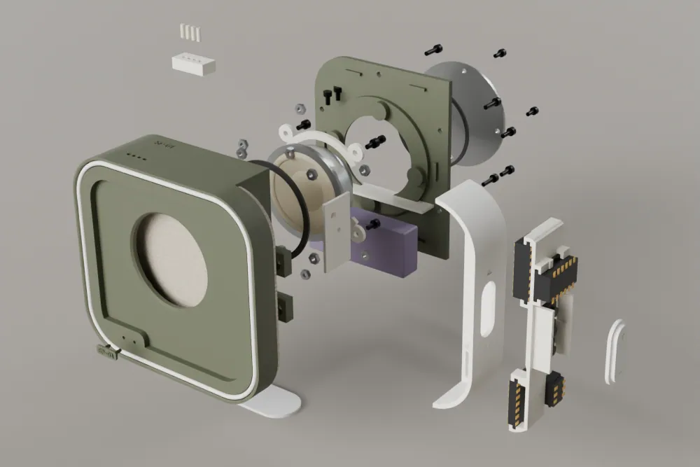
Callouts
FIG. 4- 01Prepare, plug the drains and paint the parts
- 02Press the nuts into the band
- 03Fit the radiator on the back plate
- 04Fit the drivers on the baffle
- 05Fit the light fibres and the LEDs
- 06Fit out the end block
- 07Fit the end block onto the band
- 08Fit the cell and the strap
- 09Join the wires and seal the pass-throughs
- 10Lay the cloth
- 11Roll the cord in
- 12Trim the cloth
- 13Seal and close the back
- 14Fit the feet
- 15Fit the badge
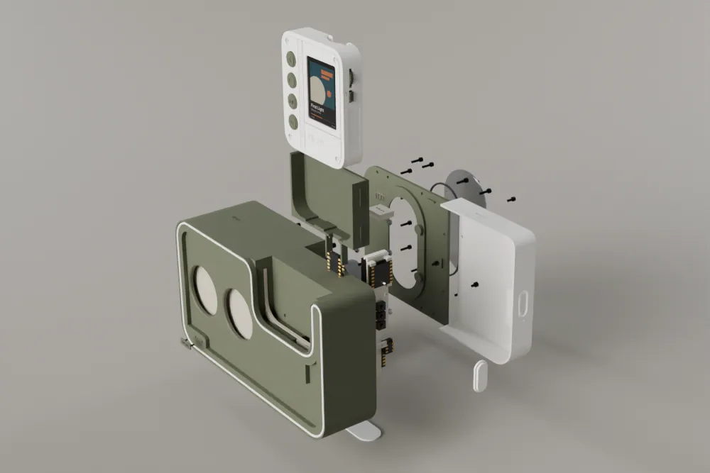
Callouts
FIG. 4- 01Prepare, plug the drains and paint the parts
- 02Press the nuts into the band
- 03Fit the radiator on the back plate
- 04Fit the drivers on the baffle
- 05Fit the light fibres and the LEDs
- 06Fit out the end block
- 07Fit the end block onto the band
- 08Join the wires and seal the pass-throughs
- 09Fit the channel cup and the dock plug
- 10Lay the cloth
- 11Roll the cord in
- 12Trim the cloth
- 13Seal and close the back
- 14Fit the feet
- 15Fit the badge
- 16Drop in PK-01
-
Pocket
-
01
Prepare, plug the drains and paint the parts
band, back plate, end block, rocker, drain pins, primer, body paint, white paint, UV resin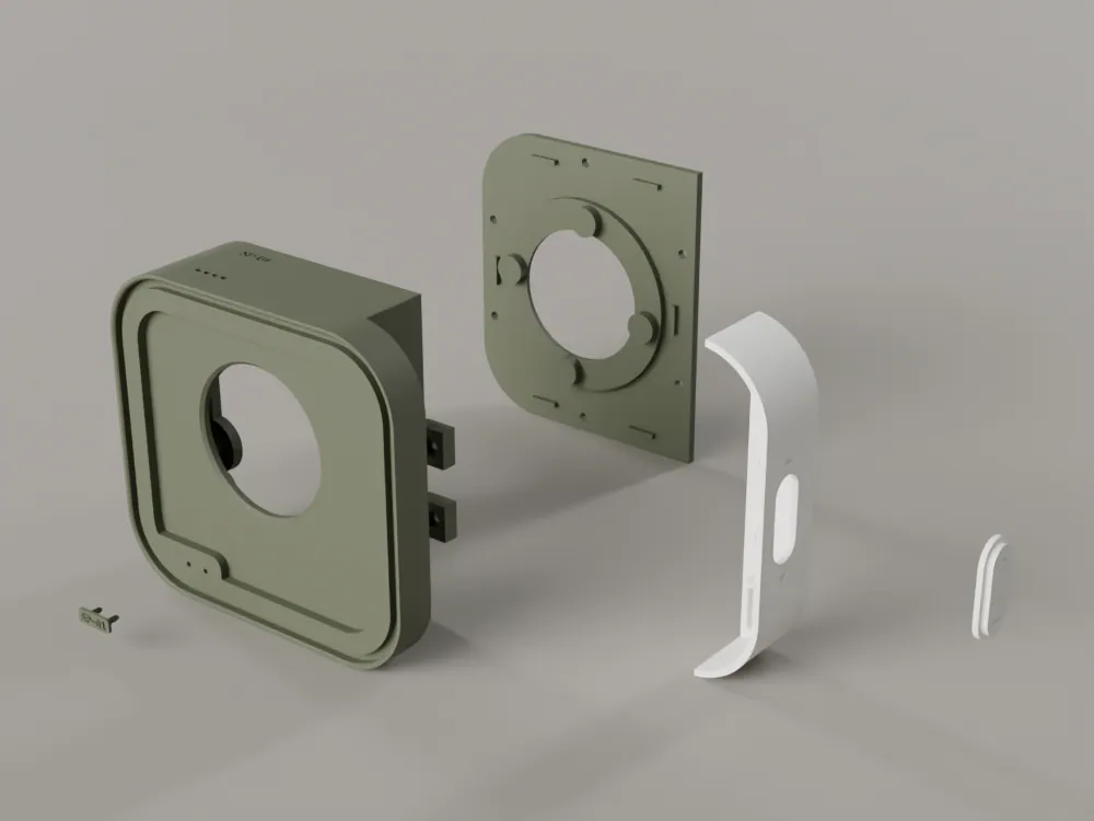
Work in a ventilated place with gloves. Wash the parts in IPA and cure them. Take the support nubs off the hidden faces named in section 04 only, never off the face, the rim or the groove, and file the stubs flat. Clear every hole with a drill held in your fingers: the 1.8 fibre holes, the screw clearance holes, the nut traps and the slot for the wires.
Plug the drains in the band. Cut each of the six drain pins off its runner to the length in the drain table (section 04), glue it into its hole with a drop of UV resin, cure it and cut it flush. The four small holes behind the baffle stay open. After this the chamber is sealed except for the lead slot and the fibre holes.
Mask the hex nut traps, the screw holes, the gland groove on the rear lip, the lead slot, the driver and radiator seats and the mating seam faces of the end block. Push a toothpick into each of the four fibre holes. Spray one thin coat of grey filler primer on the outside faces, sand it with 800 grit, and spray the flat matte paint in thin coats. One paint colour per part. The inner faces of the band stay unpainted.
Oat: Oat: band and back plate olive (near RAL 6003). End block and rocker white (near RAL 9016, matched against your cord). Cloth oat, cord white, badge olive.
Olive: Olive: band and back plate olive (near RAL 6003). End block and rocker white. Cloth heathered olive grey, cord white, badge white.
Graphite: Graphite: band and back plate graphite (near RAL 7022 Umbra grey). End block and rocker white. Cloth heathered charcoal, cord white, badge white.
Leave the light bar, the rack, the clamp plates, the driver clamp ring and the battery strap unpainted: they are hidden.
Paint the foot recess in the underside of the band in the band colour. The clear silicone feet sit over it and the colour shows through.
Tools: Flush cutters, needle files, wet and dry paper, masking tape, pin vise, toothpicks, UV torch
A length of your cord rolls into the painted groove with light resistance and no paint ridge in the corners. A nut drops into every trap.
A 1.5 mm fibre offcut enters every fibre hole, and each drain pin is flush and bonded.
The end block white and the cord white look alike side by side. If not, repaint the end block before you go on.
Thick paint. The groove is 2.2 wide with a fit that has only 0.4 of interference, and the fibre holes are 1.8 for a 1.5 fibre, so two heavy coats close them. Thin coats, and test with the cord before the last coat.
Forgetting a drain pin. A missing pin is a leak path into the sealed chamber that only shows at the seal check.
-
02
Press the nuts into the band
4 x M2 nut (driver), 6 x M2 nut (back), 2 x M2 nut (ear), masking tape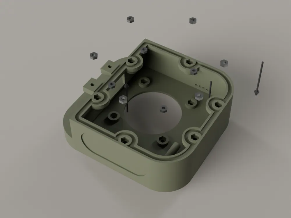
Stand the band with its open back toward you. Drop an M2 nut into each blind trap behind the baffle (the driver traps, from the chamber side), and into each trap in the rear lip for the back plate screws. The traps are 4.3 across flats and 2.0 deep, for a 4.0 nut 1.6 thick, so each nut sits 0.4 below the mouth.
Press a nut into each of the two ear traps on the notch wall. These traps open toward the front: lay a strip of tape across each mouth, or press the nut in lightly, until its screw has started.
Count them: 4 driver nuts, 6 back nuts and 2 ear nuts.
Tools: Tweezers, masking tape
Look into every trap with a torch: the nut lies flat on the floor of the trap and cannot spin.
The count of nuts in the band equals the count of screws that will enter it.
Tipping the band with loose nuts in it. They fall out. Keep the open back facing up or toward you until the screws are in, and never rely on gravity to hold a nut.
-
03
Fit the radiator on the back plate
50 mm radiator, 4 x M2 nut (radiator), 4 x M2 x 5 screw, 0.6 x foam tape (m)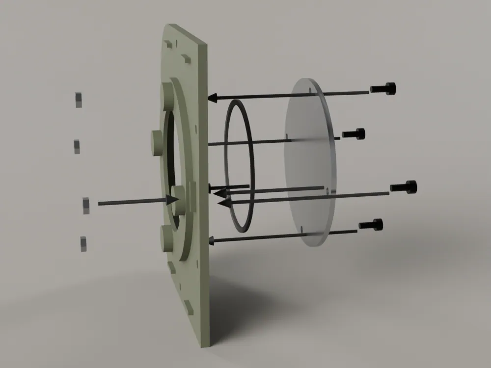
Lay the back plate outer face down on a soft cloth. Drop an M2 nut into the trap in each radiator post from the inside. Turn the plate over.
Cut the 3.0 foam tape to a ring on the land between the radiator pocket's aperture and the nut posts: slit the tape to 1.5 wide and lay it round the aperture. Set the 50 mm radiator in its 3.2 deep pocket, flange down, with its four screws at 82 degrees plus 90 each (not 45), so none meets the driver's magnet. Drive the four M2 x 5 screws until the heads seat on the flange.
The foam is squeezed to 0.9, so the flange stands 0.9 off its seat.
Tools: Tweezers, hex key, knife
The radiator stands proud of the plate by its foam only, and moves freely when you press its cone gently with a fingertip and springs back, with no scrape.
Every screw is flush on its flange and its tip is inside the nut: each thread engages the nut's full 1.6.
Over-tightening. Crushing the foam below 0.6 stops the radiator moving and ruins the tuning. Stop when the head seats.
Using the longer screw from the driver step. The M2 x 5 belongs here and the M2 x 4 behind the baffle.
-
04
Fit the drivers on the baffle
40 mm driver, clamp ring, 0.6 x foam tape (m), 4 x M2 x 4 screw (driver)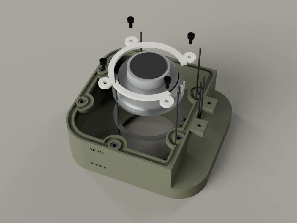
Run a ring of foam tape round the cutout on the back of the baffle (the driver's flange is a plain 40 round, 1.7 thick, with no mounting holes). Lower the 40 mm driver into the cutout from the back, cone first, so its flange lies on the foam. Set the clamp ring over the rim with the notch over the solder terminals, and drive four M2 x 4 through its ears into the blind nuts. The ring seats on the bosses.
Note which way the solder terminals point before you fit the driver. You solder the wires in step 9.
Tools: Hex key, knife
The flange or the ring sits on the boss tops with the foam squeezed to 0.9, with no foam pinched in the screw traps.
Press the cone gently with a fingertip: it moves freely, with no scrape and no rattle.
Longer screws. The driver screw is M2 x 4: a longer one passes the nut and reaches the cloth side.
-
05
Fit the light fibres and the LEDs
4 x light fibre, light bar, 4 x micro LED, UV resin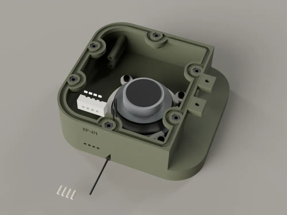
Work on the band. Slide the four micro LEDs into the pockets of the light boot bar, with their enamelled leads out through the slots at its back. Bond the bar under the top wall with a few small drops of UV resin at its ends, away from the bores, so the four bores line up with the four 1.8 holes at the front left of the top wall (pitch 2.6, from x -21.0 at y 8.4). The bar sits flat against the wall's inner face. Remove the toothpicks from the holes.
Cut four lengths of the 1.5 mm end-glow fibre, about 4.8 long, square at both ends, and polish the top ends with fine paper. From the top face, drop each fibre into its hole until it rests on its shoulder: its top end then sits 0.2 under the face. Fix it with a very small drop of UV resin and cure it with the torch.
From the left the lights are power, Bluetooth, PK-01 link and charge on the pocket (power, Bluetooth, PK-01 link and dock power on the dock).
Tools: Side cutters, UV torch, cocktail stick, fine paper
Each fibre rests on its shoulder with its end 0.2 under the face, level and square, and no gap shows round it.
The LED leads leave the back of the bar through their slot and are not pinched between the bar and the wall.
Resin on the fibre end, which clouds the light, and resin that runs into the aperture. Use a very small drop.
A 2.0 mm fibre. It does not clear the 2.6 pitch.
-
06
Fit out the end block
end block, rocker, module rack, controller, amp board, booster, charger, 3 x tact switch, hookup wire, STEMMA QT lead, PH socket lead, resistors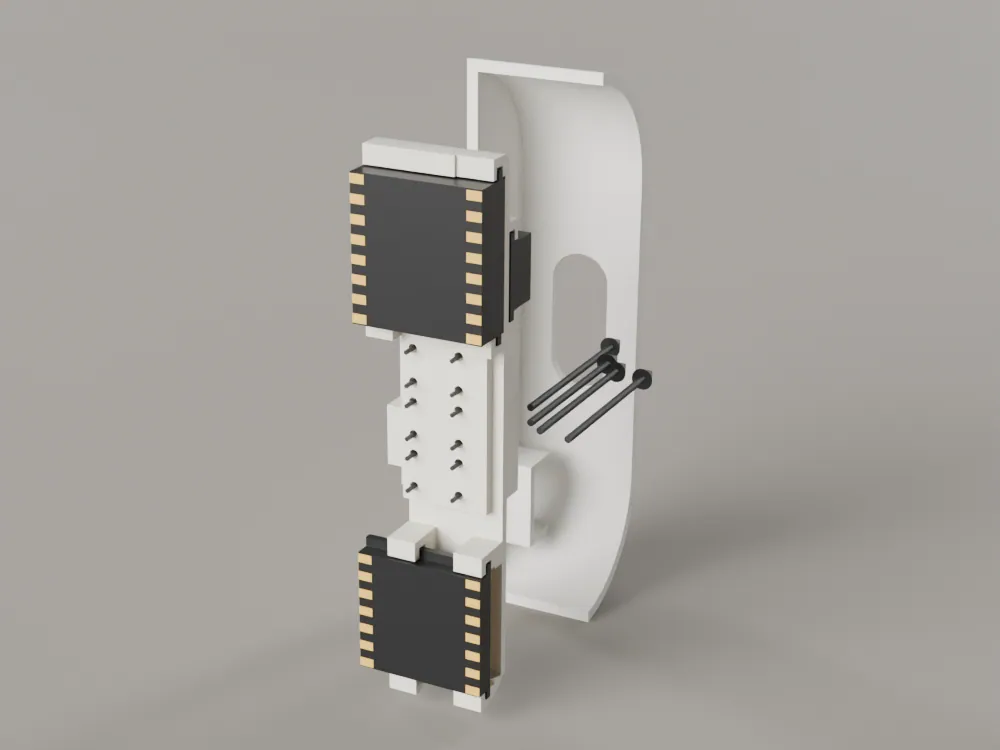
Work with the block off the band. Drop the rocker into the block from the inside: its flange sits behind the end wall.
Press the charger module into its boot in the end block, behind the back opening, until its hooks hold it. Its USB-C mouth stands 0.5 behind the outer face. This is the unit's outside port: it charges, it does not flash.
Seat the three tact switches in the rack's switch seat with their legs through the seat floor: the two 160 gf switches at the ends, the 260 gf switch in the centre, at a pitch of 7.2. Solder the four wires behind the floor: three keys and a common ground.
Slide the modules into the rack along y, into their card slots (each slot is the board's thickness plus 0.25 a side): the controller with its antenna end up and its USB-C end down, the booster on the outer side of the spine, and the amp in the inner column, lowest. The controller and the booster click past a printed latch finger. The amp slot takes a board up to 19.4 long.
Solder the wires between the modules with the rack still out of the block, as in the wiring table (section 05). Flash the controller now (section 06), while its USB-C is open to the bench. Leave the wires for the driver, the lights and the cell long, trailing out of the open face. Lower the rack into the end block along +x from the open side until its rails bear on the end wall's inner face; the block's guides hold it, and in the next step the foam pads on the ears press it home.
Tools: Tweezers, multimeter, soldering iron
Every module sits square in its slots and cannot rock, and the input's mouth is 0.5 behind the outer face.
Press each end of the rocker, and its centre: you feel the centre switch click, and an end press does not click the centre.
Forcing a module into its slot, or pinching a wire between the rack and the block. If it does not slide, back out and look.
Soldering the switch wires after the rack is in the block. They are soldered behind the seat floor, with the rack on the bench.
-
07
Fit the end block onto the band
end block, 2 x M2 x 6 screw (block), 0.6 x foam tape (m)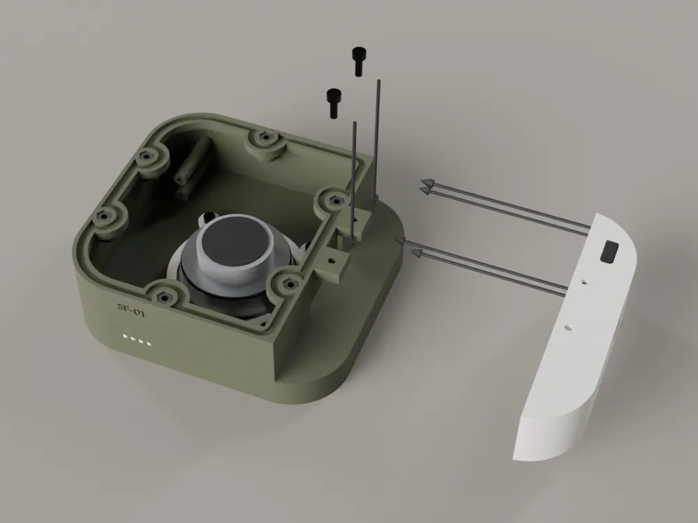
Stick a short piece of the foam tape (about 5 long) on the tip of each ear on the notch wall. The ears stop 0.9 short of the rack, and the foam pushes it onto the end wall. Feed the free ends of the wires through the lead slot in the notch wall, then slide the block onto the band along -x, so the ears go into its cavity and its seam faces meet the notch walls.
Drive the two M2 x 6 screws in from behind: through the back wall of the block into the ear nuts, with a straight driver along -y. Nothing stands behind the back face. Snug is enough: resin cracks.
The free ends of the wires now hang in the chamber, ready for step 9.
Tools: Straight 1.5 mm hex driver, scissors
The block's top and end follow the band outline exactly: the corner reads as one flush wrap, with no step. The seam faces meet the notch walls.
The rocker still moves, and no wire is trapped at a seam.
Dragging the wires taut through the slot, which pulls a joint off its pad. Pay them out as the block slides on.
-
08
Fit the cell and the strap
cell, battery strap, 2 x M2 x 4 screw (strap)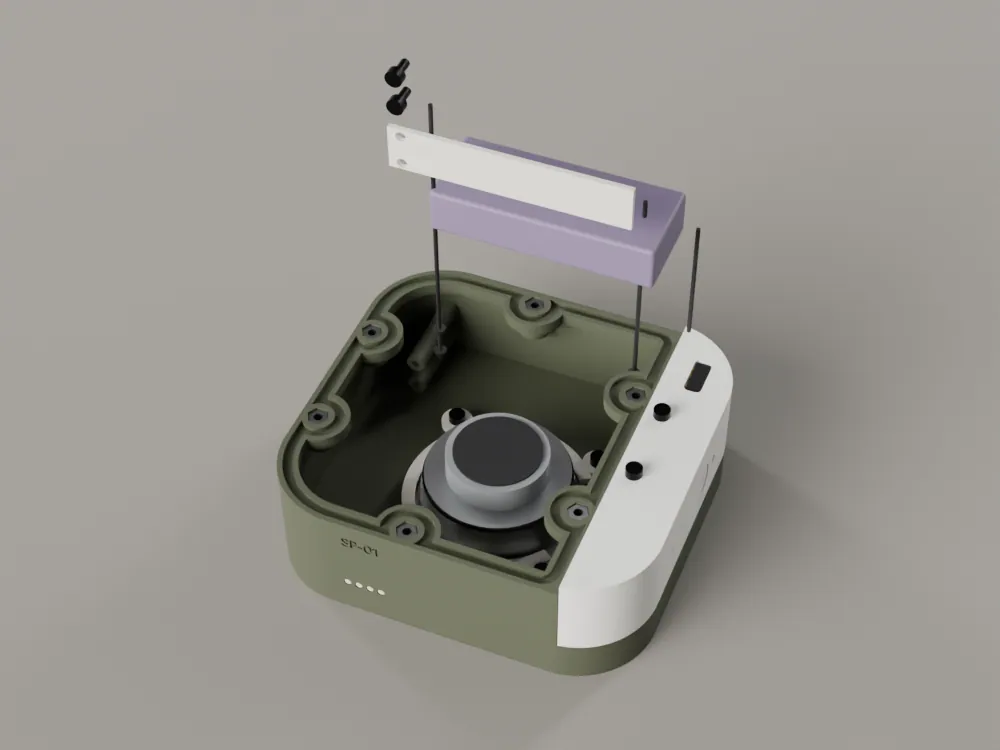
Pass the cell, with its plug free, through the lead slot in the notch wall into the chamber (the slot is 13 x 26, the cell 10 x 20). Stand it on its long edge on the chamber floor from x -25 to 25.4, under the driver. Lay the battery strap across its top edge and drive two M2 x 4 into the two posts at its left end. Leave the 0.5 swelling gap the bay allows.
Leave the cell unplugged until step 9, and keep its plug clear of metal.
Tools: Hex key, callipers
The cell stands 0.5 under the driver's basket and 0.3 in front of the back bosses, and the strap holds it without squeezing. The bay takes 10.5 x 20.5 x 50.4 at most.
A multimeter on the cell's plug reads 3.6 to 4.2 V, with the plug right way round.
A bigger cell. A 102060 or a wider pouch does not fit, and a cell that presses on the driver or the strap is a swelling risk.
-
09
Join the wires and seal the pass-throughs
hookup wire, clamp plate (end block), 0.6 x foam tape (m), sealant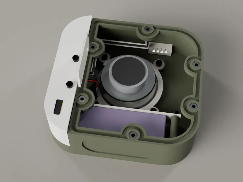
Three bundles cross the lead slot in the notch wall at different heights: the cell wires, the driver wires and the light wires. Solder the amp's OUT+ and OUT- wires to the two terminals of the 40 mm driver, shortest path, leaving a little slack (red to +).
Solder each light's two leads: one to its GPIO wire through its 1 k series resistor, the other to the common ground wire, covering each joint with heat shrink. Scrape the enamel off a micro LED lead before you tin it. The 1 k keeps each light to well under 1 mA from the 3.3 V pad: bright enough through a fibre, gentle on the cell and inside the pad's limit, and the firmware sets the brightness with PWM.
With a multimeter on the amp end of the driver wires, read about 3 to 4 ohm: a 4 ohm driver.
Seal each lead slot on the chamber side: a strip of foam tape over the slot, a bead of neutral cure sealant, and a clamp plate pressed into it so the plate is bedded all round and the wires are surrounded. Hold the plate with a strip of masking tape until the sealant skins (about 30 minutes), and let it cure for 24 hours.
Last, plug the cell into the PH socket lead. Keep the cell on an insulating surface until then.
Tools: Soldering iron, multimeter, cocktail stick, masking tape
A driver wire tugged lightly does not move at the plate, and no gap shows round the wires.
Each plate has a continuous sealant bead round it, with no strand of wire or foam crossing it.
Sealing the plate but not between the wires: air runs along a wire. Work sealant round each insulation, then close the plate.
Reversed driver wires. Keep red to + and black to - on every driver.
Plugging the cell in before the wires are checked. Note the cell's polarity before you plug it in.
-
10
Lay the cloth
cloth, masking tape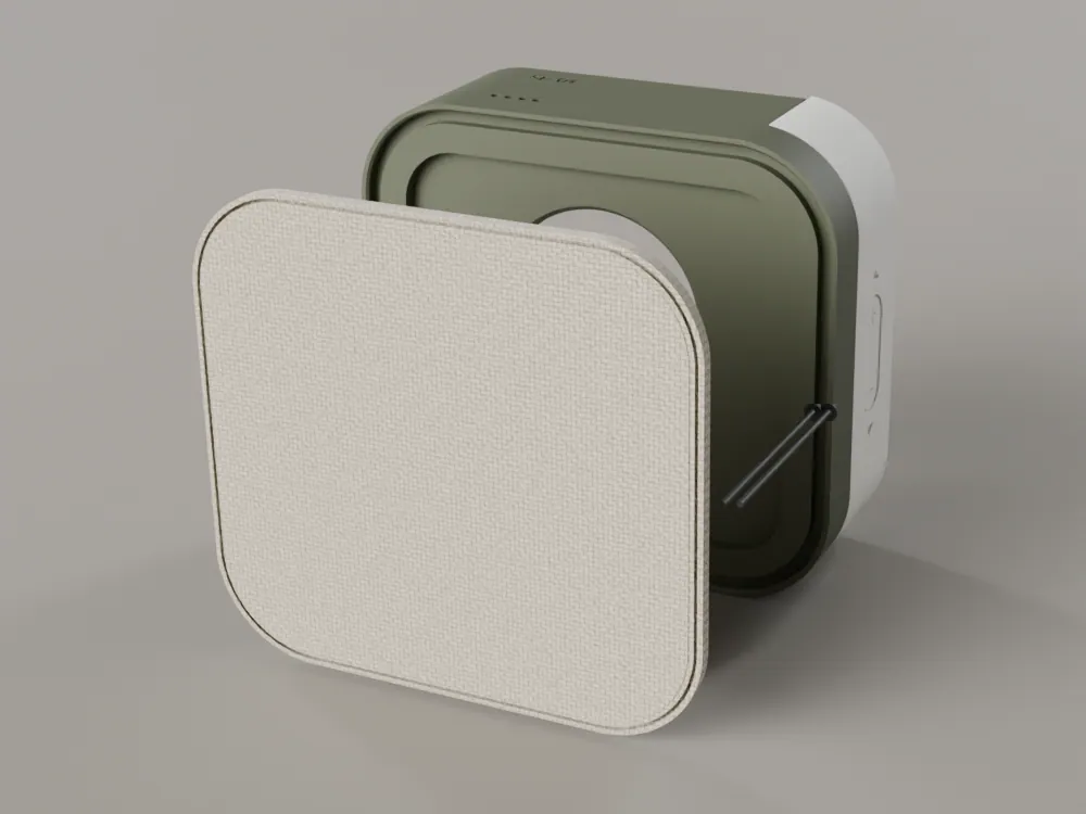
Cut the cloth blank: the face outline plus 8 all round, so you have enough to hold and pull. Draw the outline on card first and cut the card as a template if you like. Keep the weave square to the face edges.
Lay the blank over the face, with the weave straight, and tape its edge to the back of the band with a few strips of masking tape, lightly. There is no glue anywhere: the cord holds the cloth.
Tools: small scissors, masking tape
The cloth lies over the whole face and past the groove, with the weave straight and no wrinkle across the face.
A skewed weave. Once the cord is in, a skewed weave shows as a diagonal on the face. Take it out and start again.
-
11
Roll the cord in
0.7 x silicone cord (m)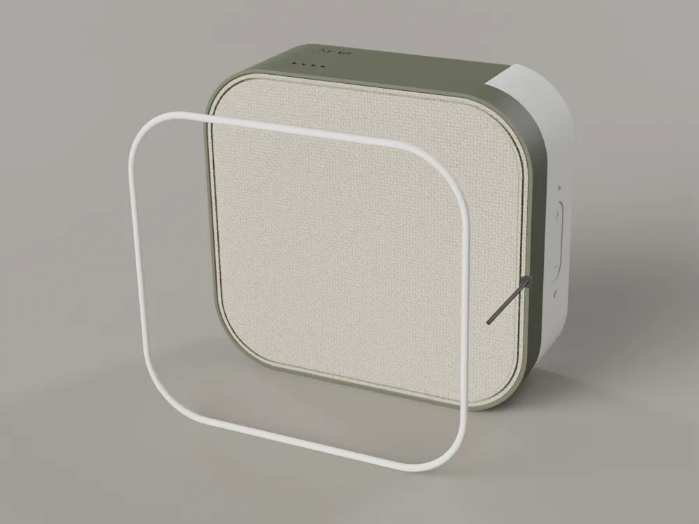
Cut the cord to the loop length, with a few millimetres of spare: about 287 (measured along the centreline).
Start at the bottom centre of the outer edge. Roll the cord into the groove with the spline roller, keeping light tension on the cloth ahead of the roller: the cord pulls the cloth taut as it goes in, under the cord and up its sides. Go round the corners slowly: the groove centreline is R15.7.
Finish where you started, at the bottom centre, with a single butt join: cut the cord so the two ends meet. The fit holds the join and no glue is needed.
Tools: Spline roller
The cord crown stands 0.1 below the face line, as a line and not a bead, all round.
The butt join is closed and sits at the bottom centre, where it is never seen.
Rolling from a corner or pulling the cloth too hard. Start at the bottom centre, and keep the tension light and even: the cord does the work.
-
12
Trim the cloth
cloth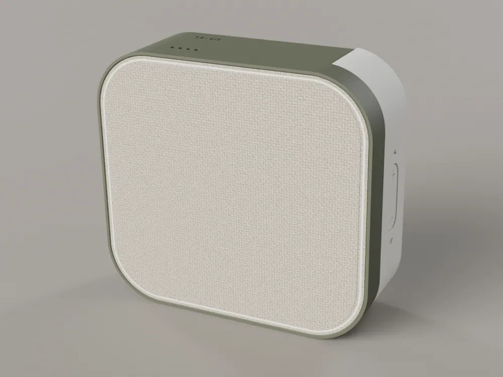
Trim the excess with a sharp knife, with the blade angled into the groove and riding on the 0.4 x 45 degree chamfer on the rim's inner top edge. The cut edge then sits 0.4 down and tucks between the cord and the rim. Use a fresh blade.
Tools: Snap-off knife
No cloth shows outside the cord, and the cut edge is tucked behind the cord all round, with no fraying.
Rework is easy: pull the cord out and the cloth comes free. The band and the cord are reusable.
Cutting into the cord, or slicing the cloth short of the groove. The chamfer guides the blade: let it ride there.
-
13
Seal and close the back
back plate, 6 x M2 x 8 screw, 0.7 x silicone cord (m), sealant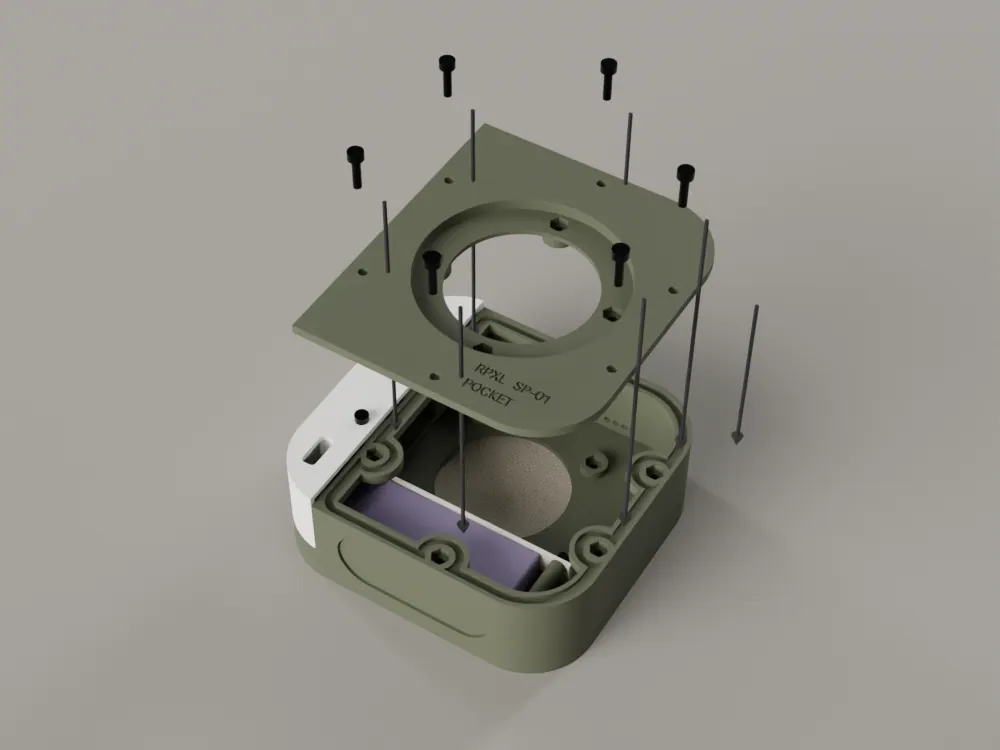
Before you close it, check what is inside: the lights soldered, the driver wires soldered, the lead slot sealed and cured, the cell strapped and plugged in. First power-up (section 09) works with the back plate off: you may test first.
Lay the cord in the gland groove round the band's rear lip: 2.2 wide and 1.2 deep, running round every screw boss. Cut it to length with the ends butted (about 270 mm).
Seat the back plate on the rear lip: the small tabs on its inner face sit just inside the lip with 0.2 of play. Drive the six M2 x 8 screws, working round in a cross pattern so the plate closes evenly.
Tools: Hex key, cocktail stick, multimeter
The plate sits flat with a 0.05 seam all round and no step at the outline.
Seal check: press the driver cone gently with a fingertip, through the cloth. The radiator on the back moves out, and eases back when you let go, as a sealed chamber does. If it does not move, or you hear a hiss, air is escaping: open the back and find the leak.
A screw in the wrong place. Every back screw sits outside the seal: if a screw does not line up with a nut, the cord has pushed the plate off its tabs.
Crossing a screw into a nut. Start each by hand.
-
14
Fit the feet
clear silicone sheet, sealant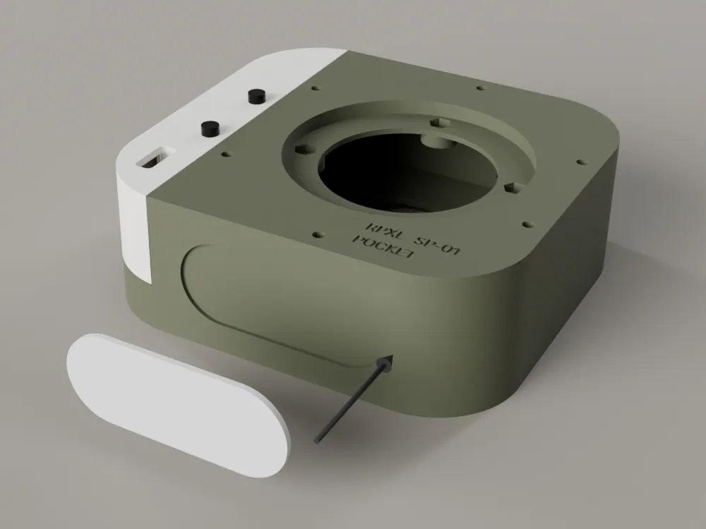
Cut one pill 44 x 17.6 from the clear sheet, drawing the outline on the sheet. It sits in the recess in the underside, centred at x -2.
Spread a thin film of clear neutral cure sealant in each recess with a cocktail stick, and press the pill in. The recess is the sheet's thickness less 0.4 deep (0.8 with 1.2 sheet, 0.6 with 1.0), so the foot stands 0.4 proud.
Tools: snap-off knife, cocktail stick
Every foot stands 0.4 proud and level, with the band colour showing through it, and the speaker sits on the feet without rocking.
Too much sealant, which squeezes out round the pill and shows. A film, not a bead.
-
15
Fit the badge
badge, badge paint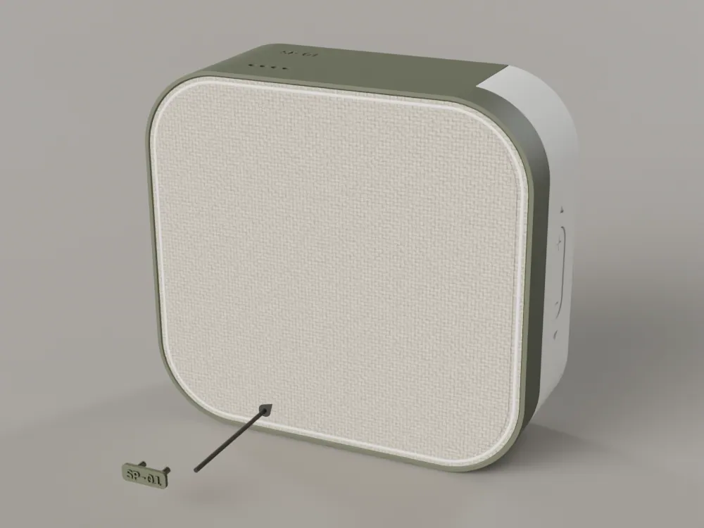
Print the badge on your home printer, letters up on light supports under the back, and the pegs with it. Wash and cure it. Paint it in one flat colour (olive on oat, white on olive and graphite).
The pocket badge is 10 x 3.6, at the bottom left of the cloth, on a true offset of 4 from the cord's inner edge.
Press the two pegs through the knit into the two 1.3 holes in the badge tab behind the cloth. Each has a 1.0 core with four crush ribs to 1.5 across: they crush in the smallest hole.
Tools: Small brush
The badge lies flat on the cloth and does not turn. Its letters read SP-01, raised.
Tug the badge lightly: it holds.
Painted pegs. Paint on the pegs closes the fit; paint the face only.
-
Dock speaker
-
01
Prepare, plug the drains and paint the parts
band, back plate, end block, rocker, channel cup, drain pins, primer, body paint, white paint, face tone paint, UV resin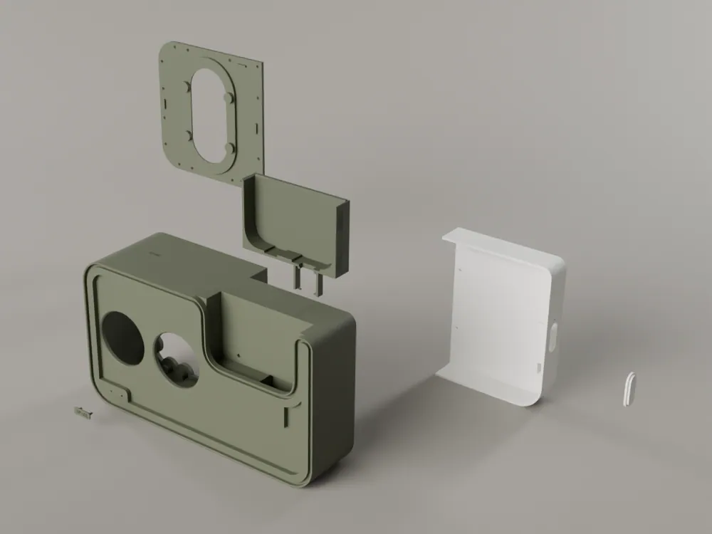
Work in a ventilated place with gloves. Wash the parts in IPA and cure them. Take the support nubs off the hidden faces named in section 04 only, never off the face, the rim or the groove, and file the stubs flat. Clear every hole with a drill held in your fingers: the 1.8 fibre holes, the screw clearance holes, the nut traps and the slot for the wires.
Plug the drains in the band. Cut each of the three drain pins off its runner to the length in the drain table (section 04), glue it into its hole with a drop of UV resin, cure it and cut it flush. After this the one chamber is sealed except for the lead slots and the fibre holes.
Mask the hex nut traps, the screw holes, the gland groove on the rear lip, the lead slots, the driver and radiator seats and the mating seam faces of the end block. Push a toothpick into each of the four fibre holes in the end block's top wall. Spray one thin coat of grey filler primer on the outside faces, sand it with 800 grit, and spray the flat matte paint in thin coats. One paint colour per part. The inner faces of the band stay unpainted.
Oat: Oat: band and back plate olive (near RAL 6003). End block and rocker white (near RAL 9016, matched against your cord). Cloth oat, cord white, badge olive.
Olive: Olive: band and back plate olive (near RAL 6003). End block and rocker white. Cloth heathered olive grey, cord white, badge white.
Graphite: Graphite: band and back plate graphite (near RAL 7022 Umbra grey). End block and rocker white. Cloth heathered charcoal, cord white, badge white.
Paint the channel cup in the face tone: 434838 on the olive colourways, 35332F on graphite. It is the liner you see round PK-01.
Leave the light bar, the rack, the clamp plates, the driver clamp ring and the battery strap unpainted: they are hidden.
Paint the foot recess in the underside of the band in the band colour. The clear silicone feet sit over it and the colour shows through.
Tools: Flush cutters, needle files, wet and dry paper, masking tape, pin vise, toothpicks, UV torch
A length of your cord rolls into the painted groove with light resistance and no paint ridge in the corners. A nut drops into every trap.
A 1.5 mm fibre offcut enters every fibre hole, and each drain pin is flush and bonded.
The end block white and the cord white look alike side by side. If not, repaint the end block before you go on.
Thick paint. The groove is 2.2 wide with a fit that has only 0.4 of interference, and the fibre holes are 1.8 for a 1.5 fibre, so two heavy coats close them. Thin coats, and test with the cord before the last coat.
Forgetting a drain pin. A missing pin is a leak path into the sealed chamber that only shows at the seal check.
-
02
Press the nuts into the band
8 x M2 nut (driver), 14 x M2 nut (back), 2 x M2 nut (ear), masking tape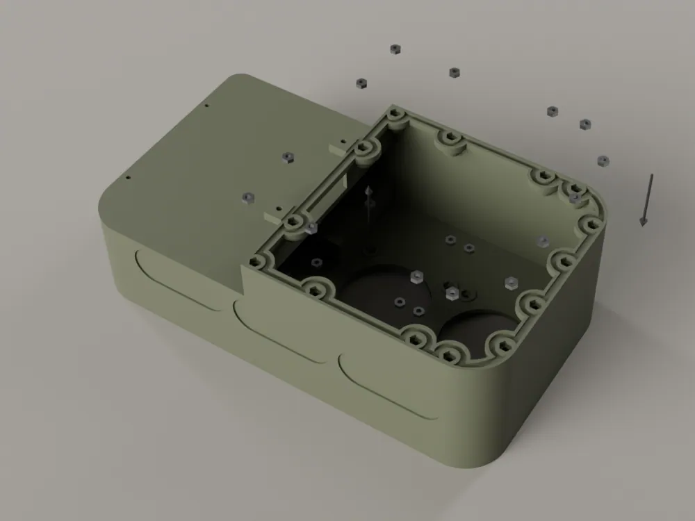
Stand the band with its open back toward you. Drop an M2 nut into each blind trap behind the baffle (the driver traps, from the chamber side), and into each trap in the rear lip for the back plate screws. The traps are 4.3 across flats and 2.0 deep, for a 4.0 nut 1.6 thick, so each nut sits 0.4 below the mouth.
Press a nut into each of the two ear traps on the notch wall. These traps open toward the front: lay a strip of tape across each mouth, or press the nut in lightly, until its screw has started.
Count them: 8 driver nuts, 14 back nuts and 2 ear nuts.
Tools: Tweezers, masking tape
Look into every trap with a torch: the nut lies flat on the floor of the trap and cannot spin.
The count of nuts in the band equals the count of screws that will enter it.
Tipping the band with loose nuts in it. They fall out. Keep the open back facing up or toward you until the screws are in, and never rely on gravity to hold a nut.
-
03
Fit the radiator on the back plate
50 x 90 radiator, 4 x M2 nut (radiator), 4 x M2 x 5 screw, 0.8 x foam tape (m)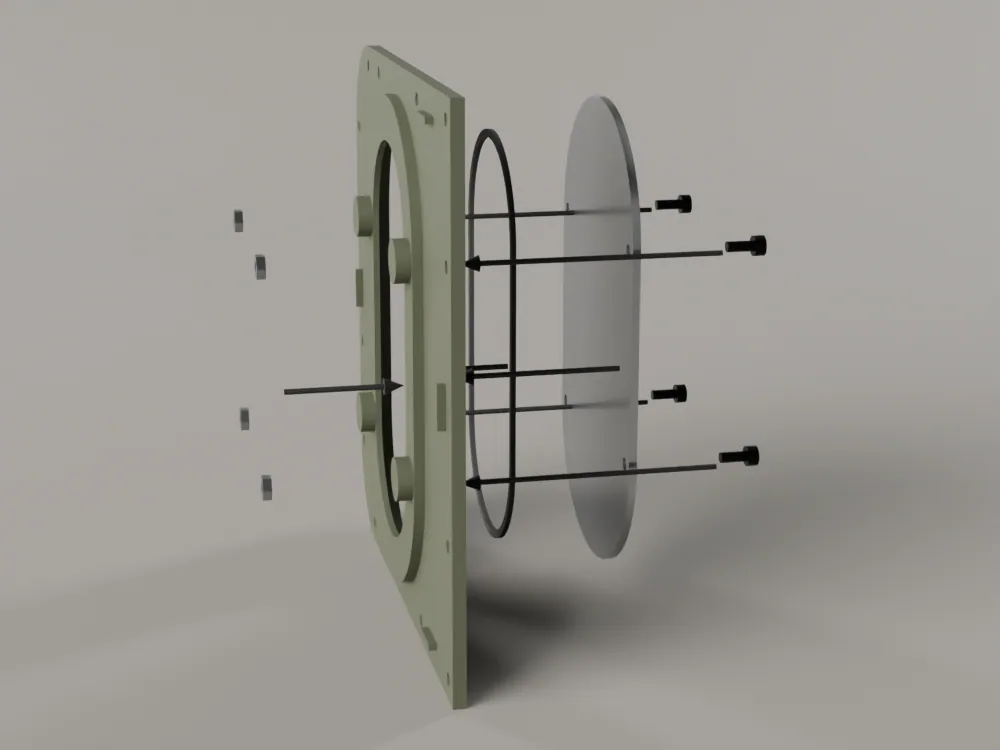
Lay the back plate outer face down on a soft cloth. Drop an M2 nut into the trap in each radiator post from the inside. Turn the plate over.
Cut the 3.0 foam tape to a ring on the land between the radiator pocket's aperture and the nut posts: slit the tape to 1.5 wide and lay it round the aperture. Set the 50 x 90 racetrack radiator in its pocket, vertical, flange down. Drive the four M2 x 5 screws until the heads seat on the flange.
The foam is squeezed to 0.9, so the flange stands 0.9 off its seat.
Tools: Tweezers, hex key, knife
The radiator stands proud of the plate by its foam only, and moves freely when you press its cone gently with a fingertip and springs back, with no scrape.
Every screw is flush on its flange and its tip is inside the nut: each thread engages the nut's full 1.6.
Over-tightening. Crushing the foam below 0.6 stops the radiator moving and ruins the tuning. Stop when the head seats.
Using the longer screw from the driver step. The M2 x 5 belongs here and the M2 x 4 behind the baffle.
-
04
Fit the drivers on the baffle
2 x 45 mm driver, 0.8 x foam tape (m), 8 x M2 x 4 screw (driver)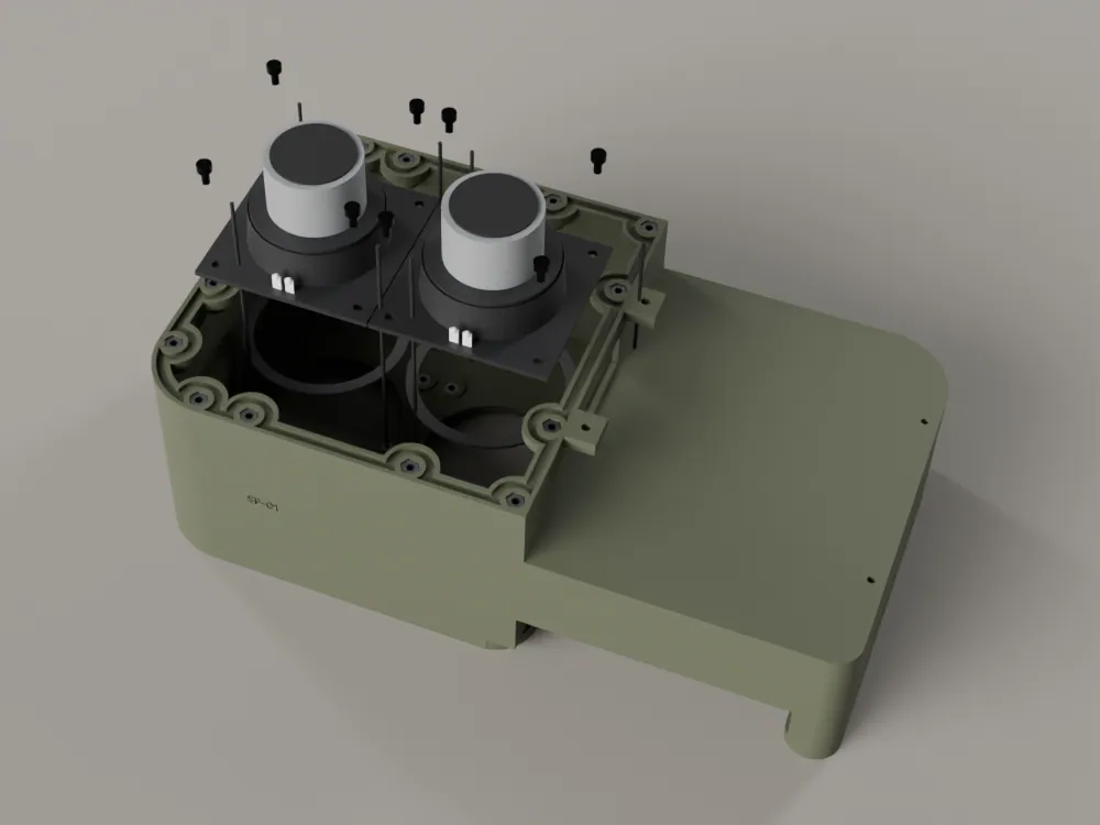
Run a ring of foam tape round each cutout on the back of the baffle. Lower each DMA45-4 into its cutout from the back, cone first, so the 46 square flange lies on the foam, and drive four M2 x 4 through the flange into the blind nuts. The flange sits on the tops of the bosses, which squeeze the foam to 0.9. Both drivers share the one chamber.
Note which way the solder terminals point before you fit the driver. You solder the wires in step 8.
Tools: Hex key, knife
The flange or the ring sits on the boss tops with the foam squeezed to 0.9, with no foam pinched in the screw traps.
Press the cone gently with a fingertip: it moves freely, with no scrape and no rattle.
Longer screws. The driver screw is M2 x 4: a longer one passes the nut and reaches the cloth side.
-
05
Fit the light fibres and the LEDs
4 x light fibre, light bar, 4 x micro LED, UV resin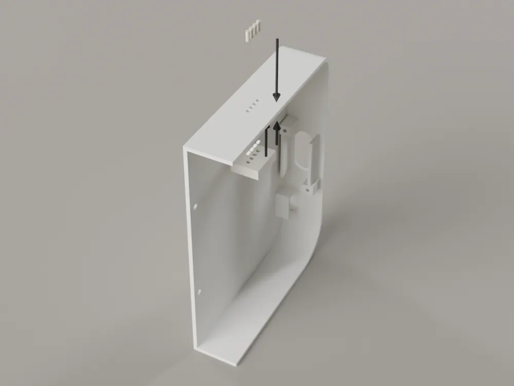
Work on the end block alone. Slide the four micro LEDs into the pockets of the light boot bar, with their enamelled leads out through the slots at its back. Bond the bar under the block's top wall with a few small drops of UV resin at its ends, away from the bores, so the four bores line up with the four 1.8 holes in the top wall (pitch 2.6, centred on the channel). The bar sits flat against the wall's inner face. Remove the toothpicks from the holes.
Cut four lengths of the 1.5 mm end-glow fibre, about 4.0 long, square at both ends, and polish the top ends with fine paper. From the top face, drop each fibre into its hole until it rests on its shoulder: its top end then sits 0.2 under the face. Fix it with a very small drop of UV resin and cure it with the torch.
From the left the lights are power, Bluetooth, PK-01 link and charge on the pocket (power, Bluetooth, PK-01 link and dock power on the dock).
Tools: Side cutters, UV torch, cocktail stick, fine paper
Each fibre rests on its shoulder with its end 0.2 under the face, level and square, and no gap shows round it.
The LED leads leave the back of the bar through their slot and are not pinched between the bar and the wall.
Resin on the fibre end, which clouds the light, and resin that runs into the aperture. Use a very small drop.
A 2.0 mm fibre. It does not clear the 2.6 pitch.
-
06
Fit out the end block
end block, rocker, module rack, controller, 2 x amp board, USB-C input, 3 x tact switch, hookup wire, STEMMA QT lead, resistors, resettable fuse, capacitor, 2 x M2 x 6 screw (rack)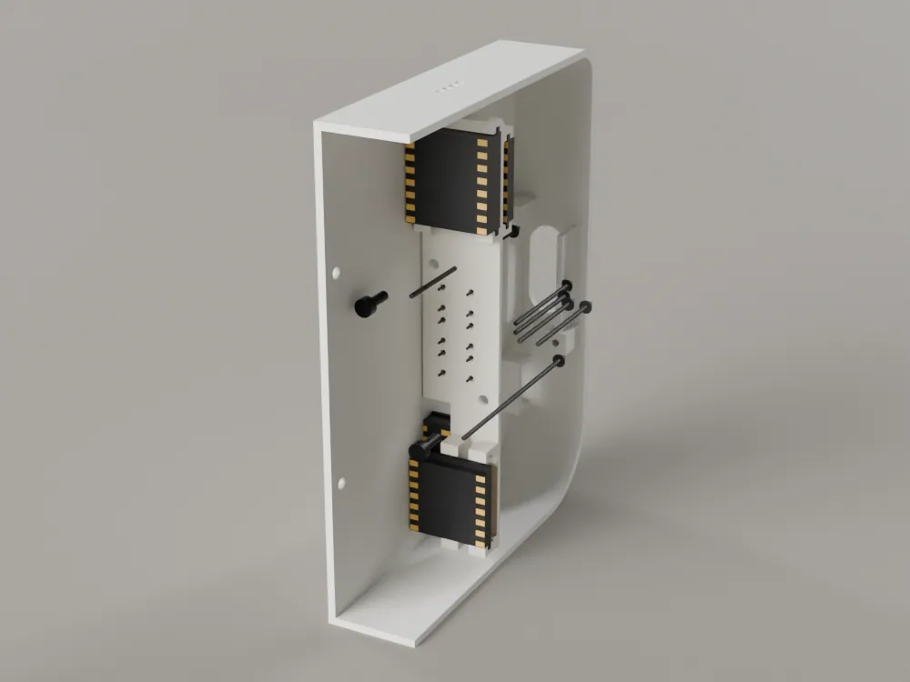
Work with the block off the band. Drop the rocker into the block from the inside: its flange sits behind the end wall.
Press the USB-C input breakout into its cradle in the end block, behind the back opening, until it holds. Its USB-C mouth stands 0.5 behind the outer face. This is the unit's outside port.
Seat the three tact switches in the rack's switch seat with their legs through the seat floor: the two 160 gf switches at the ends, the 260 gf switch in the centre, at a pitch of 7.2. Solder the four wires behind the floor: three keys and a common ground.
Slide the controller and the left amp into their card slots on the rack plate's inner face (the controller with its antenna end up and its USB-C end down), and the right amp into its slots on the outer face above the lugs. Each slot is the board's thickness plus 0.25 a side. The amp slots take a board up to 19.4 long.
Solder the wires between the modules with the rack still out of the block, as in the wiring table (section 05), including the dock lead: three wires of about 250 with the resettable fuse in the VBUS wire and the 10 k resistor from 5 V to the CC wire, their far ends left trailing. Flash the controller now (section 06), while its USB-C is open to the bench. Leave the wires for the drivers long, trailing out of the open face. Lower the rack into the end block along +x from the open side until its plate bears on the two lugs, and drive the two M2 x 6 screws through the plate into the tapped lugs with the straight driver.
Solder the 1000 uF capacitor across the amps' 5 V supply, long lead to the 5 V side.
Tools: Tweezers, multimeter, soldering iron
Every module sits square in its slots and cannot rock, and the input's mouth is 0.5 behind the outer face.
Press each end of the rocker, and its centre: you feel the centre switch click, and an end press does not click the centre.
Forcing a module into its slot, or pinching a wire between the rack and the block. If it does not slide, back out and look.
Soldering the switch wires after the rack is in the block. They are soldered behind the seat floor, with the rack on the bench.
-
07
Fit the end block onto the band
end block, 2 x M2 x 6 screw (block), 0.8 x foam tape (m)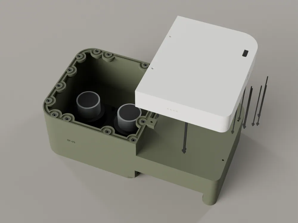
Stick a short piece of the foam tape (about 5 long) on the tip of each ear on the notch wall. Feed the free ends of the wires through the lead slot in the notch wall, then slide the block onto the band along -y from the back, so the ears go into its cavity and its seam faces meet the notch walls.
Drive the two M2 x 6 screws in from behind: through the back wall of the block into the ear nuts, with a straight driver along -y. Nothing stands behind the back face. Snug is enough: resin cracks.
The free ends of the wires now hang in the chamber, ready for step 8.
Tools: Straight 1.5 mm hex driver, scissors
The block's top and end follow the band outline exactly: the corner reads as one flush wrap, with no step. The seam faces meet the notch walls.
The rocker still moves, and no wire is trapped at a seam.
Dragging the wires taut through the slot, which pulls a joint off its pad. Pay them out as the block slides on.
-
08
Join the wires and seal the pass-throughs
hookup wire, clamp plate (end block), 0.8 x foam tape (m), sealant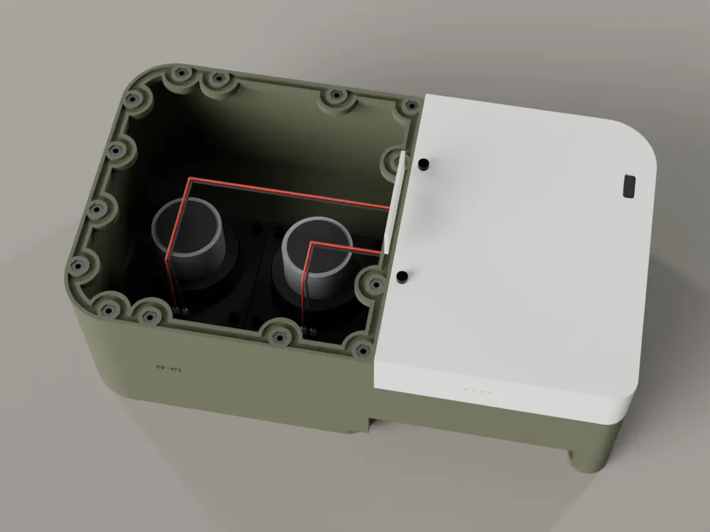
Two driver runs and the dock lead cross the lead slot in the notch wall. Solder the left amp's OUT+ and OUT- wires to the two terminals of the left driver and the right amp's to the right driver, shortest path, leaving a little slack (red to +).
Solder each light's two leads: one to its GPIO wire through its 1 k series resistor, the other to the common ground wire, covering each joint with heat shrink. Scrape the enamel off a micro LED lead before you tin it. The 1 k keeps each light to well under 1 mA from the 3.3 V pad: bright enough through a fibre and inside the pad's limit, and the firmware sets the brightness with PWM.
With a multimeter on the amp end of the driver wires, read about 3 to 4 ohm: a 4 ohm driver.
Seal each lead slot on the chamber side: a strip of foam tape over the slot, a bead of neutral cure sealant, and a clamp plate pressed into it so the plate is bedded all round and the wires are surrounded. Hold the plate with a strip of masking tape until the sealant skins (about 30 minutes), and let it cure for 24 hours.
Leave the dock lead's free ends for step 9.
Tools: Soldering iron, multimeter, cocktail stick, masking tape
A driver wire tugged lightly does not move at the plate, and no gap shows round the wires.
Each plate has a continuous sealant bead round it, with no strand of wire or foam crossing it.
Sealing the plate but not between the wires: air runs along a wire. Work sealant round each insulation, then close the plate.
Reversed driver wires. Keep red to + and black to - on every driver.
-
09
Fit the channel cup and the dock plug
channel cup, plug breakout, clamp plate (plug bay), 2 x M2 x 3 screw, 0.8 x foam tape (m), sealant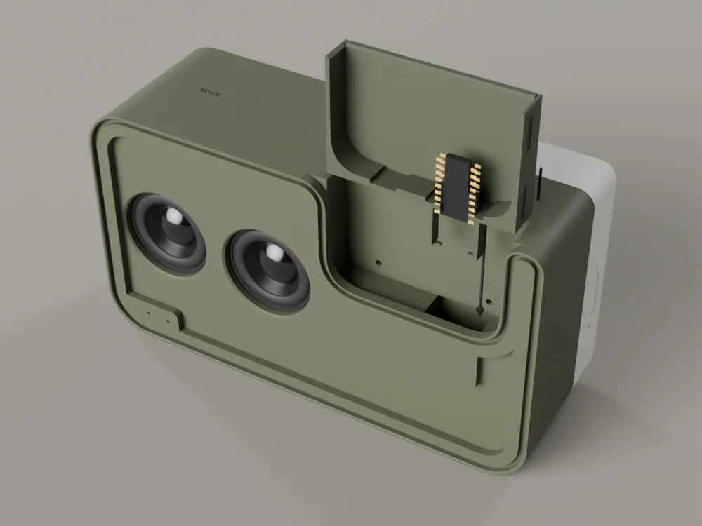
Solder the free ends of the dock lead's three wires to the plug breakout's VBUS, GND and CC pads, with the 5.1 k resistor on the breakout left in place. Keep the joints flat: the back face of the board has only 0.9 of height.
Slide the breakout into the cage under the cup's ledge from the front, until its bottom corners rest on the two lips and the wires leave under the rear bridge. The plug floats 0.5 either way in its hole.
Feed the wires' free length through the plug bay slot into the chamber, then drop the cup into its pocket from the top, so the cage lips go into the two pockets in the baffle. From the chamber side, drive two M2 x 3 through the spine back wall into the cup's tapped holes: tightening closes the 0.2 gap. Seal the bay slot with foam tape, sealant and its clamp plate, as in step 8.
Check the dock lead against the wiring table (section 05): VBUS through the fuse, GND, and CC with its 10 k to 5 V.
Tools: Soldering iron, hex key, multimeter, masking tape
The plug stands in the middle of the channel's floor, 2.0 left of the channel centre, and nudges 0.5 each way without rubbing.
The cup is seated at the face: the lip opening is 61.0, the cup channel 60.6, with no step at the lip. Drop PK-01 in dry: it rests on the two ledge pads and leans onto the back wall before the plug engages.
A multimeter on the plug's pads: continuity from each pad to its wire, and none between them.
Tightening the cup screws hard. The tip stops 0.6 short of the bottom of the tap, and tightening only needs to close the gap.
Pinching the dock wires under the bridge or the breakout, or bending them sharply at the bay slot.
-
10
Lay the cloth
cloth, masking tape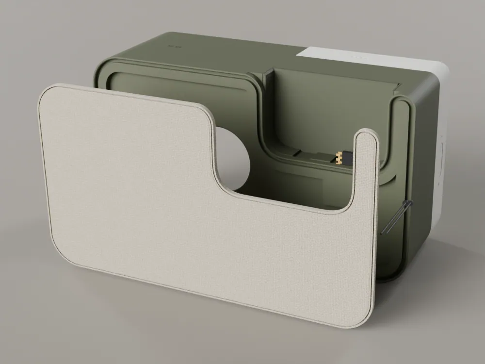
Cut the cloth blank: the face outline plus 8 all round, so you have enough to hold and pull. Draw the outline on card first, with the channel opening cut out 5 inside its edge, and cut the card as a template. Keep the weave square to the face edges. The cloth lines the channel as one piece with the face.
Lay the blank over the face, with the weave straight, and tape its edge to the back of the band with a few strips of masking tape, lightly. There is no glue anywhere: the cord holds the cloth.
Tools: small scissors, masking tape
The cloth lies over the whole face and past the groove, with the weave straight and no wrinkle across the face.
The cloth sits well inside the channel opening, with no cloth hanging over the lip.
A skewed weave. Once the cord is in, a skewed weave shows as a diagonal on the face. Take it out and start again.
-
11
Roll the cord in
1.1 x silicone cord (m)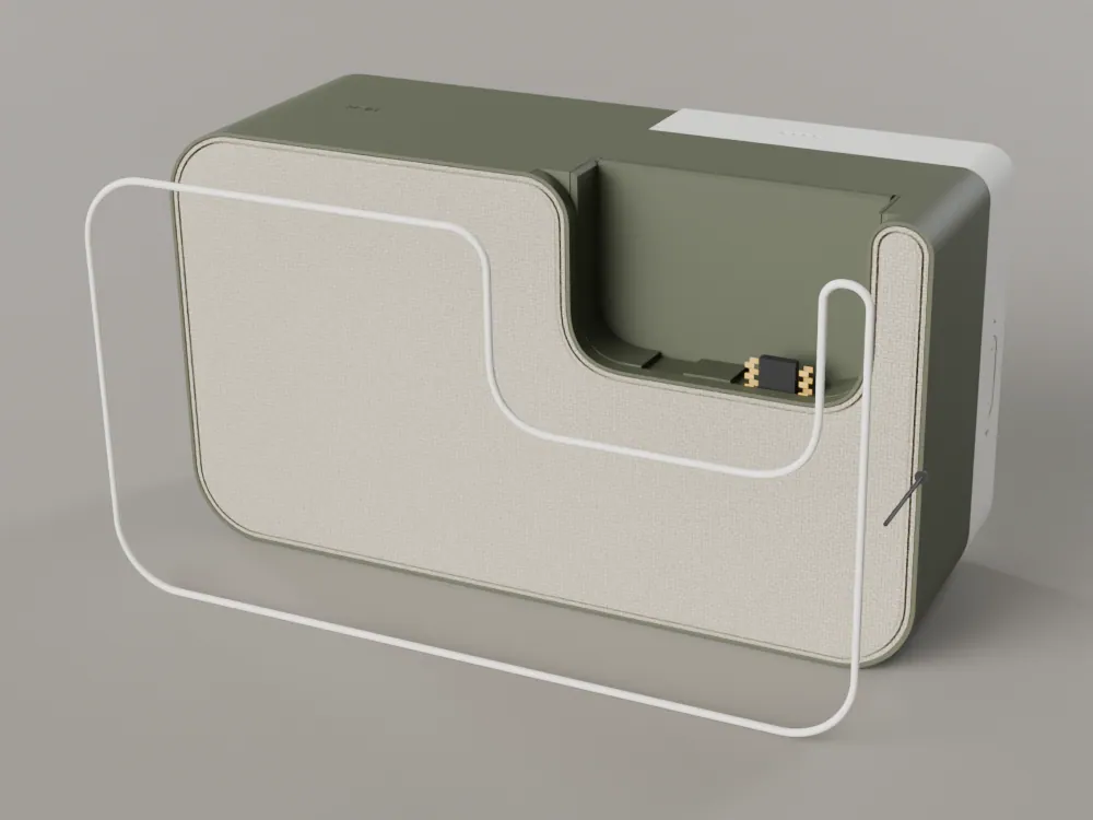
Cut the cord to the loop length, with a few millimetres of spare: about 605 (measured along the centreline).
Start at the bottom centre of the outer edge. Roll the cord into the groove with the spline roller, keeping light tension on the cloth ahead of the roller: the cord pulls the cloth taut as it goes in, under the cord and up its sides. Go round the corners slowly: the groove centreline is R27.7. Follow the one groove into the channel: round the outer edge, down into the channel through the two R8.5 mouth fillets, round the channel floor and back up. The cloth lines the channel as you go.
Finish where you started, at the bottom centre, with a single butt join: cut the cord so the two ends meet. The fit holds the join and no glue is needed.
Tools: Spline roller
The cord crown stands 0.1 below the face line, as a line and not a bead, all round.
The butt join is closed and sits at the bottom centre, where it is never seen.
Rolling from a corner or pulling the cloth too hard. Start at the bottom centre, and keep the tension light and even: the cord does the work.
-
12
Trim the cloth
cloth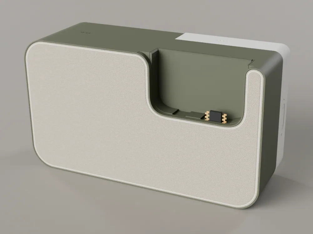
Trim the excess with a sharp knife, with the blade angled into the groove and riding on the 0.4 x 45 degree chamfer on the rim's inner top edge. The cut edge then sits 0.4 down and tucks between the cord and the rim. Use a fresh blade.
Tools: Snap-off knife
No cloth shows outside the cord, and the cut edge is tucked behind the cord all round, with no fraying.
Rework is easy: pull the cord out and the cloth comes free. The band and the cord are reusable.
Cutting into the cord, or slicing the cloth short of the groove. The chamfer guides the blade: let it ride there.
-
13
Seal and close the back
back plate, 14 x M2 x 8 screw, 1.1 x silicone cord (m), sealant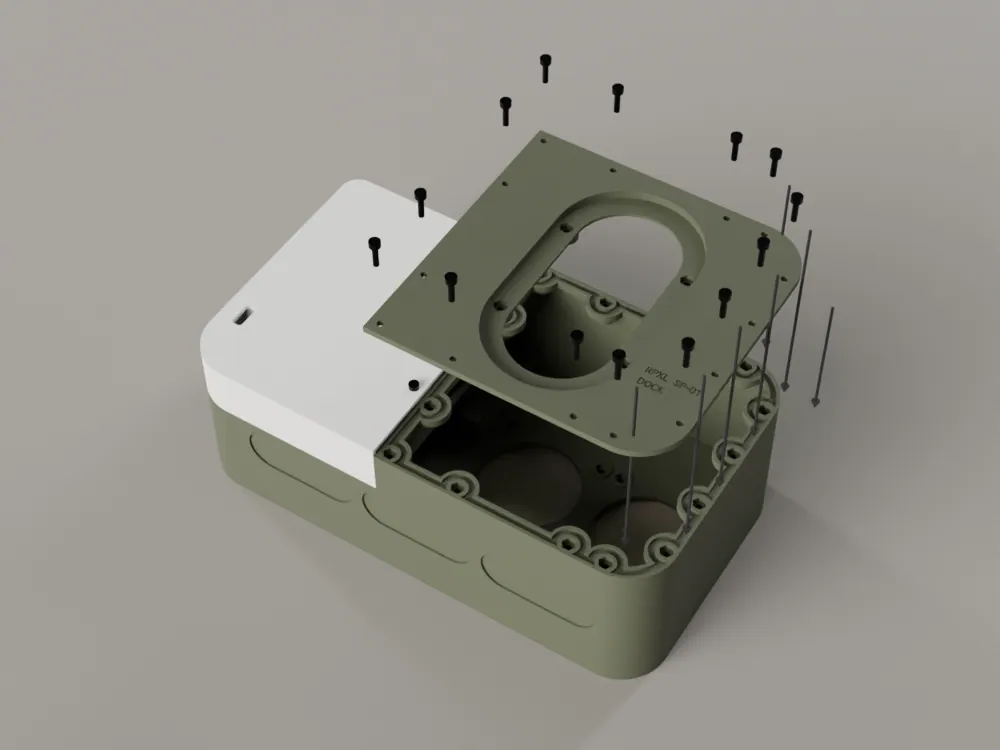
Before you close it, check what is inside: the lights soldered, both drivers soldered, the lead slots sealed and cured, the dock lead joined. First power-up (section 09) works with the back plate off, because the USB-C is on the end block: you may test first.
Lay the cord in the gland groove round the band's rear lip, round every screw boss. There is one ring and no divider. Cut it to length with the ends butted (about 380 mm).
Seat the back plate on the rear lip: the small tabs on its inner face sit just inside the lip with 0.2 of play. Drive the 14 M2 x 8 screws, working from the middle outward in a cross pattern so the plate closes evenly.
Tools: Hex key, cocktail stick, multimeter
The plate sits flat with a 0.05 seam all round and no step at the outline.
Seal check: press the driver cone gently with a fingertip, through the cloth. The radiator on the back moves out, and eases back when you let go, as a sealed chamber does. If it does not move, or you hear a hiss, air is escaping: open the back and find the leak.
A screw in the wrong place. Every back screw sits outside the seal: if a screw does not line up with a nut, the cord has pushed the plate off its tabs.
Crossing a screw into a nut. Start each by hand.
-
14
Fit the feet
clear silicone sheet, sealant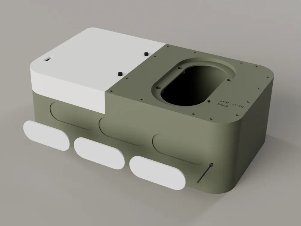
Cut three pills 44 x 17.6 from the clear silicone sheet, drawing the outlines on the sheet. They sit in the three recesses in the underside, at x -52, -4 and +44.
Spread a thin film of clear neutral cure sealant in each recess with a cocktail stick, and press the pill in. The recess is the sheet's thickness less 0.4 deep (0.8 with 1.2 sheet, 0.6 with 1.0), so the foot stands 0.4 proud.
Tools: snap-off knife, cocktail stick
Every foot stands 0.4 proud and level, with the band colour showing through it, and the speaker sits on the feet without rocking.
Too much sealant, which squeezes out round the pill and shows. A film, not a bead.
-
15
Fit the badge
badge, badge paint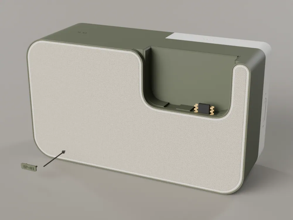
Print the badge on your home printer, letters up on light supports under the back, and the pegs with it. Wash and cure it. Paint it in one flat colour (olive on oat, white on olive and graphite).
The dock badge is 14 x 5, at the bottom left of the cloth, on a true offset of 6 from the cord's inner edge.
Press the two pegs through the knit into the two 1.3 holes in the badge tab behind the cloth. Each has a 1.0 core with four crush ribs to 1.5 across: they crush in the smallest hole.
Tools: Small brush
The badge lies flat on the cloth and does not turn. Its letters read SP-01, raised.
Tug the badge lightly: it holds.
Painted pegs. Paint on the pegs closes the fit; paint the face only.
-
16
Drop in PK-01
PK-01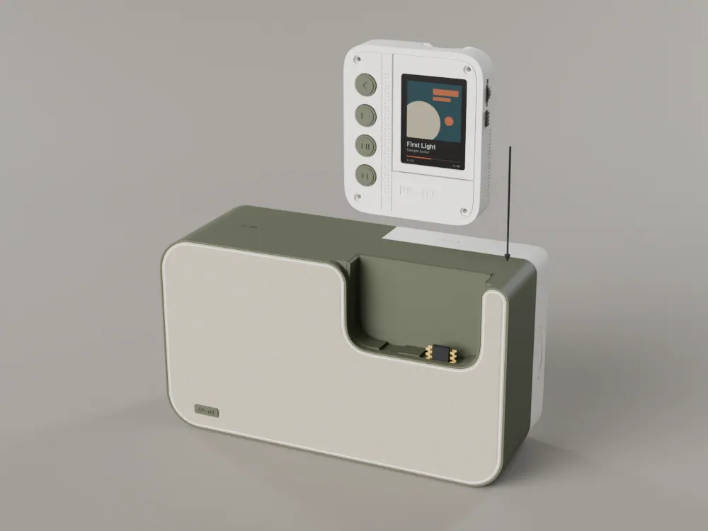
Hold PK-01 with its ports down and its screen toward you, and lower it into the channel. It stands on the two ledge pads, leans onto the back wall and the dock plug mates with its USB-C. PK-01 stands 36 proud of the top, held over 42 of its 78. Its wheel, keys, screen and hold slide are all usable when docked.
A pull toward the face is not held: PK-01 lifts out toward you, as it should.
Tools: none
PK-01 rests on the ledge pads, not on the plug, and does not rock under a thumb on the wheel.
PK-01 charges from the plug, and its music plays through the speaker over Bluetooth, paired automatically the first time it is docked.
Levering PK-01 onto the plug. Lower it straight down: the channel walls guide its last 42 mm.
Which screw goes where
Screw lengths from M2 x 3 to M2 x 8 and one nut size. There are no inserts anywhere: screws go into captive hex nuts in printed traps, or into a tapped hole. No screw shows on the face. Every thread engages at least the nut's full 1.6, and the tip stays 0.3 or more off the floor of its blind hole.
| Fastener | Qty | Where it goes |
|---|---|---|
| Screw, M2 x 8 socket cap | 6 | DIN 912, A2 stainless, black; back plate into the rear lip nuts |
| Nut, M2 hex | 6 | DIN 934, 4.0 across flats, 1.6 thick; in the rear lip traps |
| Screw, M2 x 6 socket cap | 2 | DIN 912; end block to the ear nuts |
| Nut, M2 hex | 2 | DIN 934; in the two ear traps of the notch wall |
| Screw, M2 x 4 socket cap | 4 | DIN 912; driver or clamp ring into the blind nut traps |
| Nut, M2 hex | 4 | DIN 934; in the blind traps behind the baffle |
| Screw, M2 x 5 socket cap | 4 | DIN 912; radiator into the back plate posts |
| Nut, M2 hex | 4 | DIN 934; in the traps of the back plate posts |
| Screw, M2 x 4 socket cap | 2 | DIN 912; battery strap into the two posts |
| Fastener | Qty | Where it goes |
|---|---|---|
| Screw, M2 x 8 socket cap | 14 | DIN 912, A2 stainless, black; back plate into the rear lip nuts |
| Nut, M2 hex | 14 | DIN 934, 4.0 across flats, 1.6 thick; in the rear lip traps |
| Screw, M2 x 6 socket cap | 2 | DIN 912; end block to the ear nuts |
| Nut, M2 hex | 2 | DIN 934; in the two ear traps of the notch wall |
| Screw, M2 x 6 socket cap | 2 | DIN 912; rack plate into the two tapped lugs of the end block |
| Screw, M2 x 4 socket cap | 8 | DIN 912; driver or clamp ring into the blind nut traps |
| Nut, M2 hex | 8 | DIN 934; in the blind traps behind the baffle |
| Screw, M2 x 5 socket cap | 4 | DIN 912; radiator into the back plate posts |
| Nut, M2 hex | 4 | DIN 934; in the traps of the back plate posts |
| Screw, M2 x 3 socket cap | 2 | DIN 912; channel cup from the chamber side into its tapped holes |
First power-up
This checks the whole unit. The firmware is in firmware/README.md.
- Before power. Check the volume of the room, and that nothing metal rests on the cell's wires (pocket). Do not connect headphones or anything else: the speaker is the only output.
- Flash. The controller is flashed over its own USB-C, before the rack goes into the end block (step 6), or with the end block off (two screws) and the rack pulled out on its wires: build and flash as in section 06. The USB-C in the end block is the pocket's charger module (or the dock's input): it does not flash.
- Charge. Plug a USB-C charger into the end block. The fourth light shows charging. While it plays on USB power the charger also feeds the speaker, so a full charge happens when it is idle.
- Power. Plug the 5 V 3 A supply into the input on the end block's back face. The speaker has no battery: it is on or asleep, and the supply stays plugged in.
- Switch on. Hold the rocker centre for 2 seconds. The power light comes on (the first of the four).
- Pair. Hold the rocker centre for 6 seconds while on: pairing mode, with the Bluetooth light pulsing for 120 seconds. Pair from any phone. There is no app.
- Play. Rocker up and down is the volume. Centre press is play or pause.
- Seal check. With the back closed, press the driver cone gently: the radiator moves out and eases back (step 13).
- Dock. Drop PK-01 into the slot. The plug charges it, and PK-01 pairs with the speaker by itself the first time: when you press play on PK-01, the speaker plays PK-01 instead of the phone. It stays a Bluetooth speaker for phones.
Troubleshooting
| What you see | Likely cause | What to do |
|---|---|---|
| Printing | ||
| The cord rolls in loose, or will not roll in | the groove printed wide or narrow, or paint thick in the groove | check the cord and the groove with callipers; thin the paint; the groove is 2.2 wide, the fit 0.4 of interference at nominal |
| A light fibre will not enter its hole | paint, or a printed hole under 1.8 | clear the hole by hand with a drill of that size |
| A nut will not drop into its trap, or spins | trap printed tight or loose (4.3 across flats) | clear the trap by hand; use a strip of tape on a loose one |
| Assembly | ||
| A back screw misses its nut | the nut left its trap, or the cord pushed the plate off its tabs | open the back; reseat the nut and the cord; start screws by hand |
| A hiss when you press a driver cone, or the radiator does not move out when you press it | a leak at a pass-through, a fibre, a drain hole or the back seal | press each seam while listening; reseal the clamp plate, a fibre or a drain pin; check the back plate screws |
| A radiator or driver cone scrapes | foam pinched, a screw too long, or the radiator crushed | re-seat; M2 x 4 behind the baffle and M2 x 5 on the radiators only |
| The rocker does not click, or one end clicks the centre | the rack is off its seat, or the foam pads are missing on the ears (pocket), or a rack screw is loose (dock) | open the end block screws and reseat the rack |
| Behaviour | ||
| No lights, or one light dark | an unsoldered LED lead or resistor, or a fibre not on its LED | check the LED wires and the fibre seat |
| PK-01 charges but does not play through the dock | PK-01 does not have the dock firmware, or it is more than 0.25 m from the speaker's controller when it first pairs | update PK-01; dock it and wait a few seconds |
| It will not switch on | a flat or unplugged cell (pocket) or no 5 V supply (dock) | plug in USB-C; check the cell's plug; hold the rocker centre for 2 seconds |
Licence and credits
| What | Licence |
|---|---|
| Firmware | MIT |
| CAD, print files, this manual and its images | © 2026 Rod Leviton, RPXL / Reactive Pixels. Licensed for building for your own personal use; not for redistribution or resale |
| Fonts embedded in this page: Inter, IBM Plex Mono. Fonts in the CAD: IBM Plex Mono, and an OFL single stroke engraving font | SIL Open Font License 1.1 |
| Firmware libraries: ESP-IDF and its components | their own licences |
© 2026 Rod Leviton, RPXL / Reactive Pixels. The SP-01 page and the rest of the range: B-Side. More from the studio at reactivepixels.com.