VK-01Desk volume knob
A desk volume knob you print, wire and build yourself. Turn it to change your computer's volume, press it to mute. A soft halo rises round the knob while you turn, and a small dot lights while it is muted. USB edition: It works as a USB keyboard's media keys, so there is nothing to install.Bluetooth edition: It pairs as a Bluetooth keyboard's media keys, so there is nothing to install.
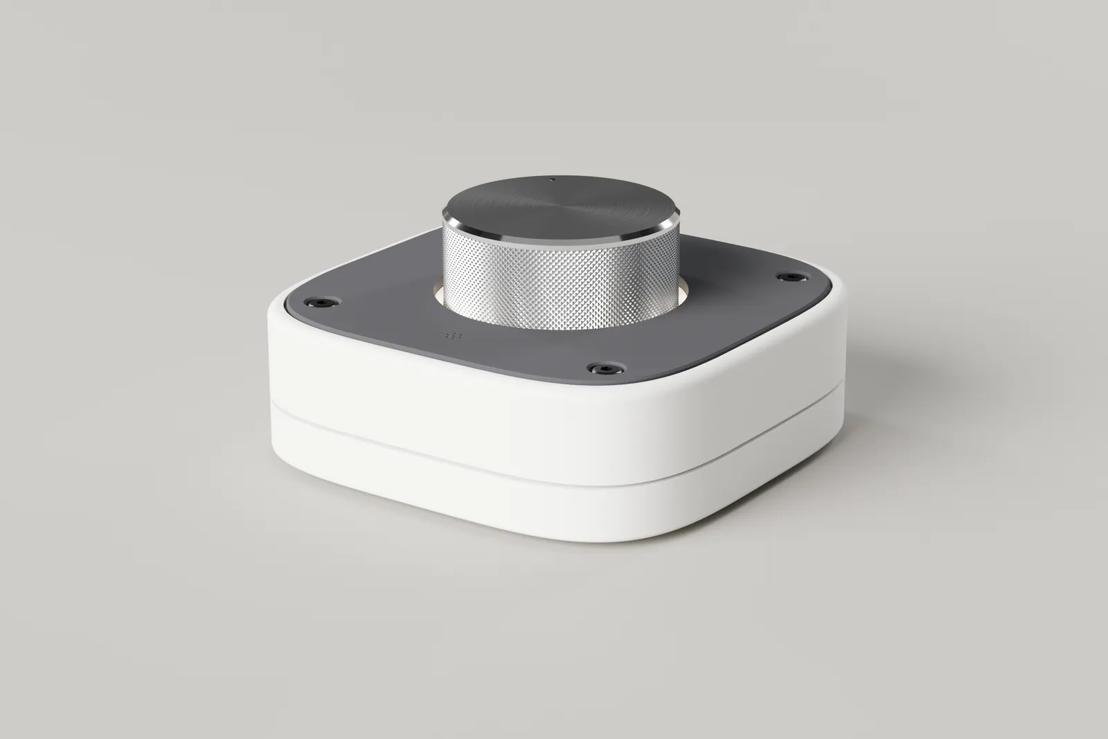
- Size
- 92 x 9246 mm to the top of a bought knob, 43 mm with the printed or CNC knob
- Weight
- 210 gabout, with the bought knob
- Controls
- Turn, pressvolume, mute
- Light
- 6 + 1 LEDhalo and mute dot
- Edition
- USBRPXL VK-01, wired
- Board
- LeonardoArduino, micro-USB
- Edition
- BluetoothRPXL VK-01 BT
- Board
- XIAOnRF52840, 1100 mAh LiPo
Which edition are you building?
One product, two editions. They share the body, deck, panel and knob; they differ in the board, the wiring and a few printed parts. Choose yours: the rest of this page then shows that edition only.
The choice is saved in this browser and written into the address (?edition=usb or ?edition=bluetooth), so a link opens the right manual. It is the only thing this page remembers.
What you're building
Two body halves, a light deck and a face panel, stacked and held by four screws. The four black screws on the face are the only fasteners you see, and they hold everything together.
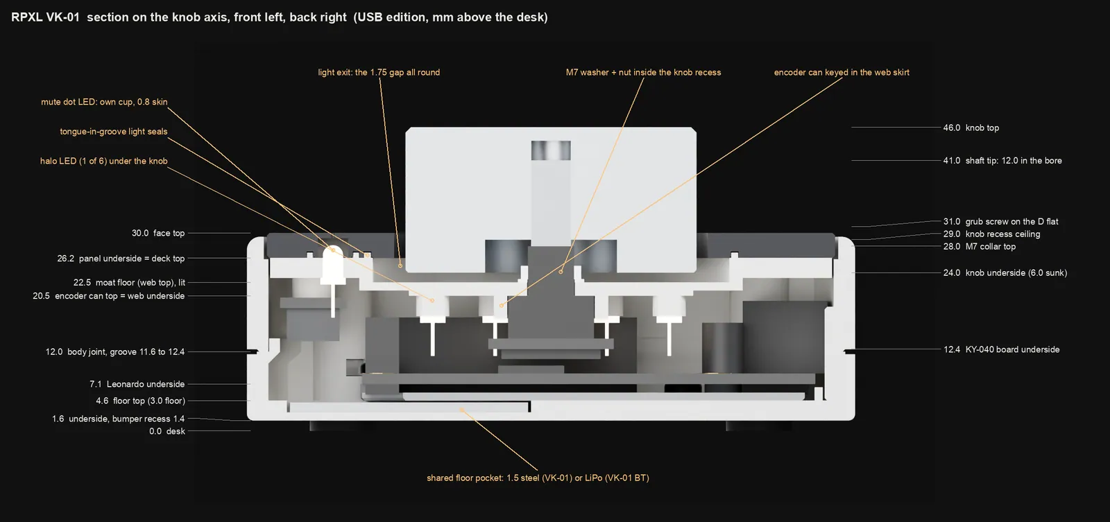
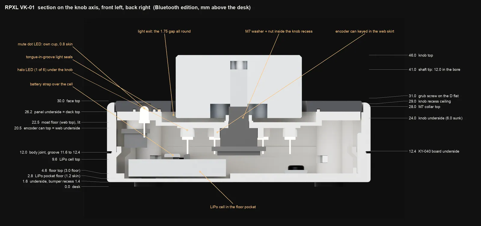
How it works
Five ideasFour screws hold it all. Four M3 x 20 button heads go down through the face panel, the light deck and the upper body into nuts held captive in the lower body.
The light deck. Under the moat round the knob, the deck clamps the encoder by its M7 nut, keys its can so it cannot turn, and holds six LEDs aimed up at the knob's underside. Their light fills a white chamber and leaves only through the 1.75 mm gap round the knob, so you see a ring, never an LED.
The mute dot. One more LED in its own light-tight cup, behind seven 0.6 mm holes in the face. When it is off, the holes are hard to find.
The board sits on a tray. The controller board sits on a small printed tray with its own hole pattern. A different board needs only a different tray, never a different body. USB edition: The tray holds an Arduino Leonardo. Bluetooth edition: The tray holds a Seeed XIAO nRF52840, and a second printed part, a strap, holds a LiPo cell in a pocket in the floor.
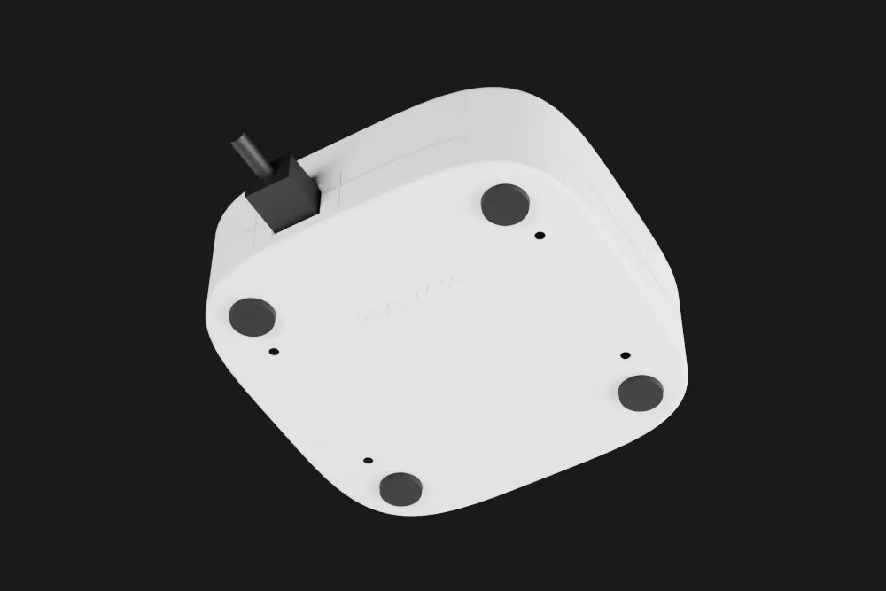
The port plate. A small printed insert at the back frames the board's own USB socket, so there is no extension cable inside. USB edition: The socket is micro-USB. Bluetooth edition: The socket is USB-C, and it also charges the cell.
The stack
mm, desk = 0| Height | What is there |
|---|---|
| 46.0 | knob top (43.0 with the printed or CNC knob, which is 19 mm tall) |
| 30.0 | face panel top |
| 24.0 | knob underside, 6.0 below the face |
| 22.5 | moat floor, lit from below |
| 20.5 | encoder can top, keyed in the deck |
| 11.6 to 12.4 | the dark groove; the body joint hides in it |
| USB edition: 7.1 | USB edition: controller board underside |
| Bluetooth edition: 7.3 | Bluetooth edition: controller board underside |
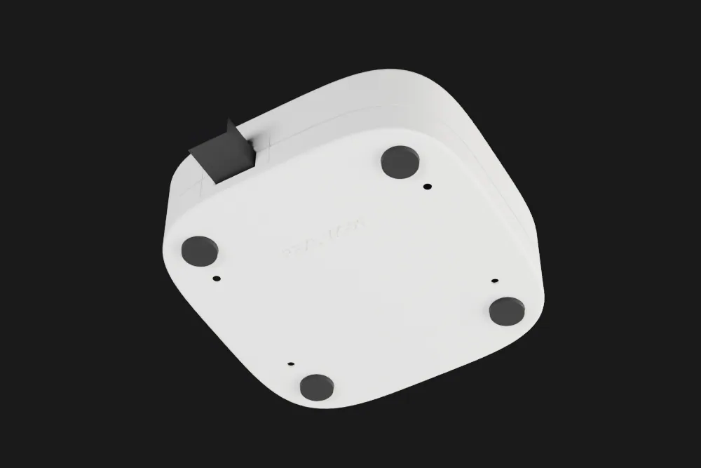
| 1.6 | body underside, on four rubber feet |
Tools and supplies
What you need besides the parts in section 03. Gather it before you start, so nothing is missing mid-step.
| Item | What it is for |
|---|---|
| Printing | |
| An MSLA resin printer with a build area of at least 170 x 100 mm and 40 mm of height | every printed part; the largest is 92 x 92 x 18 mm and the plates are laid out inside 170 x 100 |
| A slicer that can set a raft per object (for example Lychee) | only the optional sector test file holds a piece that takes a raft and one that does not; otherwise load its two pieces as separate jobs |
| Plain printer paper | levelling the build plate (not card) |
| IPA or resin cleaner, two wash containers, UV cure station | washing (dirty bath, then clean) and post-curing |
| Digital callipers | the exposure test, the 20 mm cube and the bought parts |
| Finishing | |
| Flush cutters, hobby knife | removing the deck's supports while the part is still green |
| A thin wedge scraper (or a flexible build plate) | taking large flat parts off the plate without prising or bending them |
| Wet and dry paper, 400 and 800 grit | support nubs, fit faces, between primer and paint |
| Cyanoacrylate gel or two-part epoxy | only for a printed knob (gluing the weight washer in) or a ring adapter (fixing it under the flange) |
| Pin vise with a 0.6 mm drill bit | clearing the seven mute dot holes by hand |
| M3 tap and tap handle | cutting threads in every 2.5 mm screw hole |
| Grey filler primer; flat matte white, charcoal and dark grey paint; a fine brush; masking tape | the finish: white body, charcoal face, dark groove, white light chamber |
| Electronics | |
| Soldering iron, solder, flux, heat shrink, wire strippers | every joint in the harness and on the driver perfboard |
| Multimeter | continuity, LED polarity, the transistor pinout |
| A computer with arduino-cli or the Arduino IDE | flashing the firmware (section 08) |
| Black electrical tape | closing the cut ends of the optional sector test pieces |
| Assembly | |
| 2.0 mm hex key, and the key for the knob's grub screw (1.5 mm for the M3 grub of a printed knob) | M3 button heads; the knob |
| Small spanner or nut driver for the M7 nut | clamping the encoder to the deck |
| A soft cloth | turning the finished unit over without marking the face |
| Bluetooth edition: Thin foam sheet or foam tape | padding both faces of the LiPo cell in its pocket |
| Safety | |
| Nitrile gloves, eye protection, ventilation | uncured resin, IPA, flux fumes and flying offcuts |
| Bluetooth edition: A safe place to handle the LiPo cell: no piercing, bending or shorting its leads | a damaged or shorted cell can overheat; charge it only through the XIAO's USB-C |
Parts to buy
Choose the knob first: it sets the look and the budget, and a bought or machined knob takes the longest to arrive. Any part matching the spec works. Where an example type or part number helps, it says "for example".
Choose your knob
decide firstFour ways to fill the deck opening. Everything else in the kit is the same, so the choice is yours to make on look, weight and budget. The edition parts lists below show the Mid bought knob; swap its row if you choose another.
The knob sits on the encoder's 6 mm D shaft and is held by a grub screw on the flat. Whichever you choose, its underside needs a recess about 20 mm across and 5 mm deep: it swallows the encoder's nut so the knob sits low in the moat.
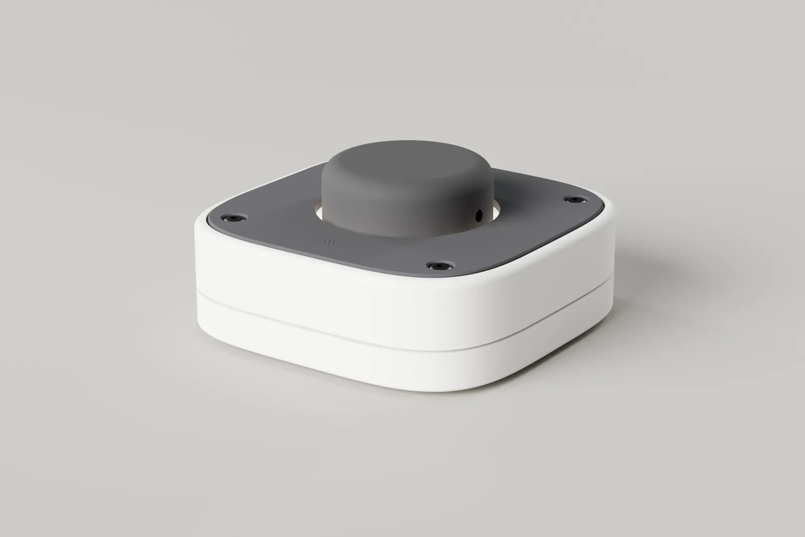
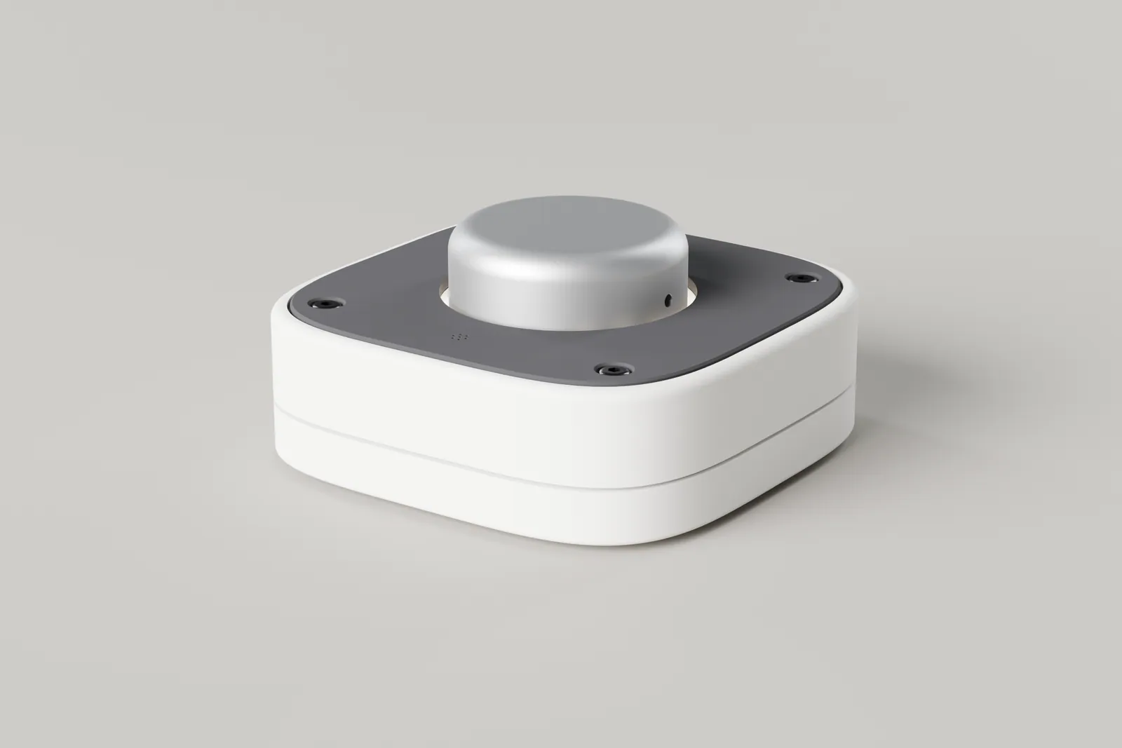
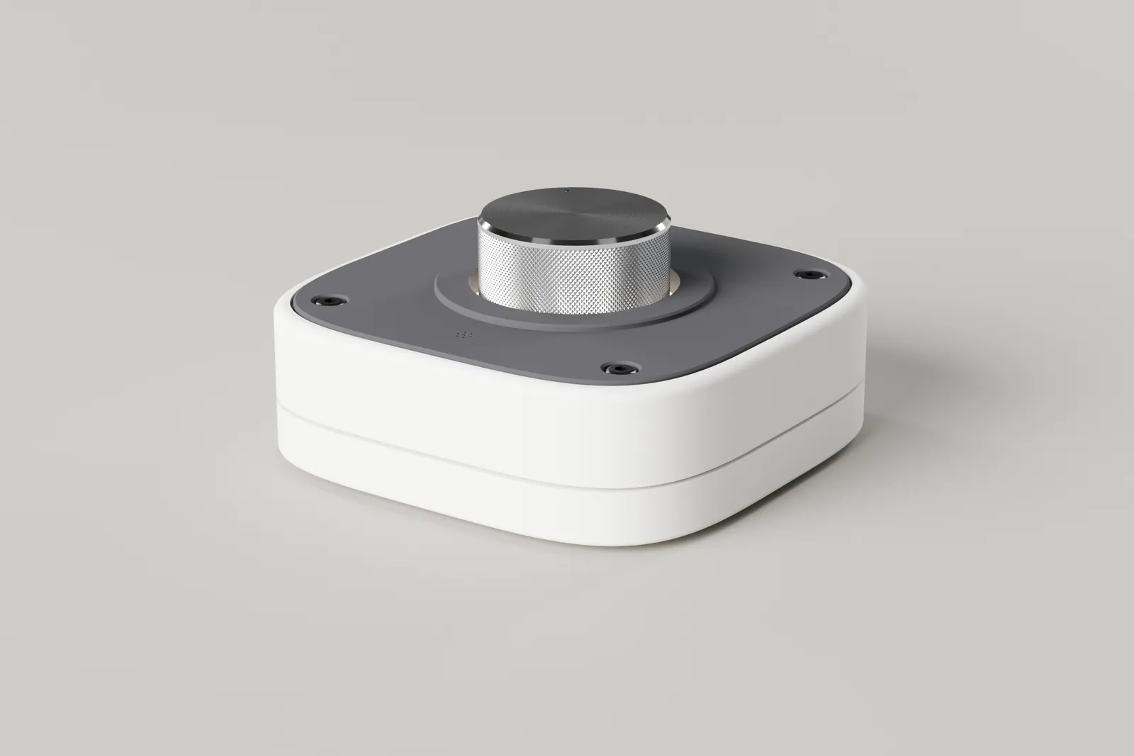
| Option | What it is | Cost, one unit (AUD) |
|---|---|---|
| Budget: printed knob | The plain 44 x 19 mm knob with a 5 mm round where the top meets the side, printed in your resin and painted flat matte. It takes an M3 x 6 grub screw, an M3 hex nut and an M20 flat steel washer (about 37 mm across, 3 mm thick) glued into the underside for weight. About 27 g bare, 44 g with the washer. | about 4 |
| Mid: bought knob | A 44 x 22 mm knurled aluminium knob with a 6 mm D bore and a side grub screw. The default in the parts lists below. | about 18 |
| Premium: CNC aluminium knob | The same plain 44 x 19 mm profile machined from 6061 aluminium, bead blasted and anodised, with a tapped M3 hole on the D flat. About 71 g. Order it from a CNC service with vk01_knob_premium.step and vk01_knob_premium_drawing_note.md from out/knob/. Coloured anodise can add 5 to 10. | about 46 to 50 |
| Your own knob, with a ring adapter | Any knob 25, 30, 35 or 40 mm across with a 6 mm D bore and a grub screw. A printed ring plugs the 47.5 mm deck opening and keeps the same 1.75 mm light gap round your knob, so the halo still shows. Print the ring for your knob's diameter. A knob up to 2 mm smaller than a ring's size also works, with a slightly wider gap. See the print notes in section 06. | your knob, plus about 1 for the ring |
Parts list
USB edition, Arduino Leonardo| Part | Qty | Spec | Fallback | Checked (2026-11-16) |
|---|---|---|---|---|
| Knob | 1 | Mid, the default: solid aluminium, 44 mm across and 22 mm tall, diamond-knurled side, 6 mm D-shaft bore about 20 mm deep, side grub screw, underside recess 20 mm across and 5 mm deep. Or one of the other choices above | ||
| Knob hardware | 1 | Budget printed knob only: one M3 x 6 grub screw, one M3 hex nut and one M20 flat steel washer (about 37 mm across, 3 mm thick) | none recorded | not individually checked, 2026-11-16 |
| Glue | 1 | Budget printed knob and ring adapters only: cyanoacrylate gel or two-part epoxy (double-sided tape also fixes a ring) | none recorded | not individually checked, 2026-11-16 |
| Controller | 1 | Arduino Leonardo (ATmega32U4, native USB) or a faithful clone | RS Australia 7617324, A$39.11, 8 in stock (listing seen, page not opened) | 2026-11-16: Core Electronics A000057 in stock, A$39.35. Pakronics out of stock; DigiKey AU has a 10 week lead time |
| Encoder | 1 | Rotary encoder module with push switch (EC11 type, for example a KY-040), M7 x 0.75 bushing, 6 mm D shaft, board about 26 x 19 mm, with its M7 nut and washer | Temperosystems, A$3.95, 9 in stock (listing seen; sold without thread, check the shaft) | 2026-11-16: Little Bird LB-00111 in stock, 60 in Sydney, A$7.65 |
| LEDs | 7 | White 3 mm through-hole, about 3.0 V at 10 mA: six for the halo, one for the mute dot | Core Electronics 25 pack of diffused 3 mm LEDs in stock | 2026-11-16: Core Electronics diffused white 3 mm LED, 25 pack, A$9.40, in stock |
| Transistor | 1 | Small NPN in TO-92 (for example 2N2222, BC337 or 2N3904) | BC337 at Core Electronics, A$0.91, in stock | 2026-11-16: Core Electronics 2N3904, A$0.43, in stock |
| Resistors | 6 | 180 ohm, 1/4 W: one per halo LED | Little Bird and Altronics also sell packs | 2026-11-16: Core Electronics 1/4 W packs of 25, A$1.60 to 1.65 (100 ohm and 1 k seen; other values not opened) |
| Resistor | 1 | 220 ohm, 1/4 W: mute dot LED | Little Bird and Altronics also sell packs | 2026-11-16: Core Electronics 1/4 W packs of 25, A$1.60 to 1.65 (100 ohm and 1 k seen; other values not opened) |
| Resistor | 1 | 1 k ohm, 1/4 W: transistor base | Little Bird and Altronics also sell packs | 2026-11-16: Core Electronics 1/4 W packs of 25, A$1.60 to 1.65 (100 ohm and 1 k seen; other values not opened) |
| Perfboard | 1 | A small offcut, cut to 16 x 10 mm, for the transistor and resistors | Core Electronics Makerverse Protoboard, A$3.10 | 2026-11-16: Core Electronics 60 x 80 mm protoboard, A$1.35, in stock (cut to size) |
| Header strip | 1 | Right-angle male pin header, to plug the harness into the Leonardo's sockets | Core Electronics breakaway right angle header, A$2.15 | 2026-11-16: Core Electronics 1 x 40 right angle male header, A$0.41, in stock |
| Screws | 4 | M3 x 20 button head, black oxide: the face screws | none recorded | not individually checked, 2026-11-16 |
| Screws | 6 | M3 x 4 button head: tray and board | none recorded | not individually checked, 2026-11-16 |
| Screw | 1 | M3 x 6 button head: driver perfboard | none recorded | not individually checked, 2026-11-16 |
| Nuts | 4 | M3 hex nuts, captive in the lower body (plus 4 more and 4 x M3 x 10 for the light test) | none recorded | not individually checked, 2026-11-16 |
| Feet | 4 | Adhesive rubber bumper feet, 10 mm across, about 3 mm tall, clear or black | Not checked | not checked at an AU source, 2026-11-16 |
| Wire | 1 | Thin stranded silicone hook-up wire, 26 to 28 AWG, and heat shrink | Core Electronics 22 AWG hookup kit, A$29.70 (thicker than spec) | 2026-11-16: Little Bird LB-PT-26AWG 5 colour silicone wire box, A$39.10, 25 in Sydney (28 AWG not found) |
| Cable | 1 | USB to micro-B, with a straight plug (USB-C or USB-A at the computer end) | Core Electronics also stocks USB-C cables | 2026-11-16: Core Electronics double ended USB-C cable 1 m, A$2.50, in stock (a micro-B cable for the USB edition was not checked) |
| Resin | 1 | A tough, opaque, paintable resin (ABS-like) | none recorded | not individually checked, 2026-11-16 |
| Paint | 1 | Grey filler primer, and flat matte paint in white, charcoal and dark grey | none recorded | not individually checked, 2026-11-16 |
AUD 57 to 122. The low end uses an Arduino Leonardo clone, the high end a genuine Arduino Leonardo.
The range above uses the Mid bought knob (AUD 17.69). With the Budget printed knob the range is about AUD 43 to 108; with the Premium CNC knob about AUD 85 to 154; with your own knob and a ring, your knob's price plus about 1 for the ring.
Approximate cost to build one, based on parts from JLC3DP, Altronics, Little Bird, Bunnings and AliExpress, October 2026. Printed parts are delivered from JLC3DP with GST added. They carry a per-part minimum and one shipping charge per order, so the first unit costs more than later ones. Paint, primer and tools are not included.
Parts list
Bluetooth edition, XIAO nRF52840| Part | Qty | Spec | Fallback | Checked (2026-11-16) |
|---|---|---|---|---|
| Knob | 1 | Mid, the default: solid aluminium, 44 mm across and 22 mm tall, diamond-knurled side, 6 mm D-shaft bore about 20 mm deep, side grub screw, underside recess 20 mm across and 5 mm deep. Or one of the other choices above | ||
| Knob hardware | 1 | Budget printed knob only: one M3 x 6 grub screw, one M3 hex nut and one M20 flat steel washer (about 37 mm across, 3 mm thick) | none recorded | not individually checked, 2026-11-16 |
| Glue | 1 | Budget printed knob and ring adapters only: cyanoacrylate gel or two-part epoxy (double-sided tape also fixes a ring) | none recorded | not individually checked, 2026-11-16 |
| Controller | 1 | Seeed XIAO nRF52840 Plus: Bluetooth LE, USB-C, built-in LiPo charger | NO CONFIRMED FALLBACK (design call). Pakronics sells only a tape-and-reel version (A$17.60, listing seen). DigiKey AU: none in stock, due 21 Dec 2026. The non-Plus XIAO nRF52840 was not found in stock, so it is unconfirmed | 2026-11-16: OUT OF STOCK now. Core Electronics A$18.25 on lead time, dispatch expected 24 to 26 Nov (counts as available with a lead time) |
| Battery | 1 | 3.7 V LiPo, about 1100 mAh, 51 x 34 x 6 mm, with protection circuit and a lead | Little Bird LB-00238, 3.7 V 1200 mAh, A$18.60, 119 in Sydney (size not confirmed against 51 x 34 x 6, check before ordering) | 2026-11-16: Core Electronics CE04377, A$8.65, NOT in stock, lead time only |
| Encoder | 1 | Rotary encoder module with push switch (EC11 type, for example a KY-040), M7 x 0.75 bushing, 6 mm D shaft, board about 26 x 19 mm, with its M7 nut and washer | Temperosystems, A$3.95, 9 in stock (listing seen; sold without thread, check the shaft) | 2026-11-16: Little Bird LB-00111 in stock, 60 in Sydney, A$7.65 |
| LEDs | 7 | White 3 mm through-hole, forward voltage 3.0 V or less at 10 mA: six for the halo, one for the mute dot | Core Electronics 25 pack of diffused 3 mm LEDs in stock | 2026-11-16: Core Electronics diffused white 3 mm LED, 25 pack, A$9.40, in stock |
| Transistor | 1 | Small NPN in TO-92 (for example 2N2222, BC337 or 2N3904) | BC337 at Core Electronics, A$0.91, in stock | 2026-11-16: Core Electronics 2N3904, A$0.43, in stock |
| Resistors | 6 | 150 ohm, 1/4 W: one per halo LED (the halo runs from the cell) | Little Bird and Altronics also sell packs | 2026-11-16: Core Electronics 1/4 W packs of 25, A$1.60 to 1.65 (100 ohm and 1 k seen; other values not opened) |
| Resistor | 1 | 100 ohm, 1/4 W: mute dot LED (3.3 V pin) | Little Bird and Altronics also sell packs | 2026-11-16: Core Electronics 1/4 W packs of 25, A$1.60 to 1.65 (100 ohm and 1 k seen; other values not opened) |
| Resistor | 1 | 1 k ohm, 1/4 W: transistor base | Little Bird and Altronics also sell packs | 2026-11-16: Core Electronics 1/4 W packs of 25, A$1.60 to 1.65 (100 ohm and 1 k seen; other values not opened) |
| Perfboard | 1 | A small offcut, cut to 16 x 10 mm, for the transistor and resistors | Core Electronics Makerverse Protoboard, A$3.10 | 2026-11-16: Core Electronics 60 x 80 mm protoboard, A$1.35, in stock (cut to size) |
| Screws | 4 | M3 x 20 button head, black oxide: the face screws | none recorded | not individually checked, 2026-11-16 |
| Screws | 2 | M3 x 4 button head: XIAO tray | none recorded | not individually checked, 2026-11-16 |
| Screws | 3 | M3 x 6 button head: battery strap (2) and driver perfboard (1) | none recorded | not individually checked, 2026-11-16 |
| Nuts | 4 | M3 hex nuts, captive in the lower body (plus 4 more and 4 x M3 x 10 for the light test) | none recorded | not individually checked, 2026-11-16 |
| Feet | 4 | Adhesive rubber bumper feet, 10 mm across, about 3 mm tall, clear or black | Not checked | not checked at an AU source, 2026-11-16 |
| Foam | 1 | A thin sheet or tape of foam, to pad both faces of the cell | Not checked | not checked at an AU source, 2026-11-16 |
| Wire | 1 | Thin stranded silicone hook-up wire, 26 to 28 AWG, and heat shrink | Core Electronics 22 AWG hookup kit, A$29.70 (thicker than spec) | 2026-11-16: Little Bird LB-PT-26AWG 5 colour silicone wire box, A$39.10, 25 in Sydney (28 AWG not found) |
| Switch | 1 | Optional: a tiny slide switch to disconnect the cell | none recorded | not individually checked, 2026-11-16 |
| Cable | 1 | USB-C, with a straight plug (USB-C or USB-A at the computer end): charging and flashing | Core Electronics also stocks USB-C cables | 2026-11-16: Core Electronics double ended USB-C cable 1 m, A$2.50, in stock (a micro-B cable for the USB edition was not checked) |
| Resin | 1 | A tough, opaque, paintable resin (ABS-like) | none recorded | not individually checked, 2026-11-16 |
| Paint | 1 | Grey filler primer, and flat matte paint in white, charcoal and dark grey | none recorded | not individually checked, 2026-11-16 |
AUD 80 to 109. The range covers the cheapest and the Australian sources for the bought parts.
The range above uses the Mid bought knob (AUD 17.69). With the Budget printed knob the range is about AUD 66 to 95; with the Premium CNC knob about AUD 108 to 141; with your own knob and a ring, your knob's price plus about 1 for the ring.
Approximate cost to build one, based on parts from JLC3DP, Altronics, Little Bird, Bunnings and AliExpress, October 2026. Printed parts are delivered from JLC3DP with GST added. They carry a per-part minimum and one shipping charge per order, so the first unit costs more than later ones. Paint, primer and tools are not included.
Print setup: calibrate first
Every fit in this kit depends on your printer printing true. Do this list before you print a single part: each item, skipped, can stop a part from fitting, and the cause is almost never where the symptom shows.
A print with one thin side, or a corner that peels off the plate, is a levelling problem, not an exposure problem. Level again with plain paper before you change any setting: an unlevelled plate causes most fit problems.
- Level the build plate with plain printer paper, not card. Loosen the plate, lay the paper on the screen, press the plate down evenly, tighten it, then set Z = 0.
- Calibrate the exposure for your resin and room temperature with an exposure test print. Choose the time at which 0.6 mm holes print open, a 6.0 mm pin fits a 6.1 mm hole, and fine detail is crisp, not swollen.
- Check the size. Print a 20 mm cube and confirm X and Y are within 0.05 mm.
- Keep the resin warm, about 25 C, and stir it before every print.
- Measure the encoder shaft. The D flat must run at least 12.0 mm down from the shaft tip, or the knob's grub screw will not land on it. If it is shorter, file the flat longer. While you have the callipers out: the threaded collar should stand 7.5 mm above the encoder can, and the shaft 13.0 mm above the collar.
- USB edition: Calliper the Arduino Leonardo against the table below. Clones vary, and the port plate and tray are drawn for these values.
- Bluetooth edition: Calliper the XIAO nRF52840 and the LiPo cell against the table below. The port plate, tray and cell pocket are drawn for these values.
Leonardo measurements
board top side upMeasure along the board from the USB edge (the short edge with the micro-USB socket and the barrel jack), and across it from the long edge nearest the barrel jack.
| What | Model value, mm | Set in |
|---|---|---|
| board size | 68.6 x 53.3 x 1.6 | LEO |
| micro-USB socket centre | 38.1 across | LEO_USB_Y |
| micro-USB overhang | 1.0 past the USB edge | LEO_USB_OVERHANG |
| barrel jack centre | 7.6 across | LEO_JACK_Y |
| barrel jack overhang | 1.8 past the USB edge | LEO_JACK_OVERHANG |
| barrel jack body | ends 11.0 along; 11.0 tall | vk01/bought.py |
| header height | 8.5 above the board | LEO_HDR_H |
| mounting holes (along, across) | (13.97, 2.54) (15.24, 50.8) (66.04, 7.62) (66.04, 35.56) | LEO_HOLES |
Every value within 0.3 mm: print as is. One differs by more: change it in params.py (or vk01/bought.py), run python print_files.py and then python -m pytest tests, and print the new files only if every test passes. The values that matter most are the micro-USB centre and overhang (the port opening allows 0.3 each side), the jack overhang (0.6 to the wall), the header height (3.5 of plug and wire room under the deck) and the first two mounting holes (they drop over printed pins).
XIAO and cell measurements
board top side upMeasure the board along its USB-C axis, and the USB-C socket from the short edge it sits on.
| What | Model value, mm | Set in |
|---|---|---|
| XIAO board size | 21.0 x 17.8 x 1.2 | XIAO |
| USB-C socket, width and height | 8.94 x 3.26 | XIAO_USBC |
| USB-C socket depth | 7.35 | XIAO_USBC |
| USB-C overhang | 1.0 past the short edge | XIAO_USBC_OVERHANG |
| LiPo cell | 51 x 34 x 6 | BATT_CELL |
| Cell pocket in the floor | 54 x 37 x 7.5 | BATT_POCKET |
Every value within 0.3 mm: print as is. One differs by more: change it in params.py (or vk01/bought.py), run python print_files.py and then python -m pytest tests, and print the new files only if every test passes. The values that matter most are the USB-C socket size and overhang, which size the port plate opening, and the cell thickness: the pocket leaves room for a thin foam pad on each face and the cell's lead.
The light test
Print the light deck and the face panel first (jobs 1 and 2 in section 06) and test the light with the real parts before you print the bodies. A pass costs no resin: the deck and panel go straight into the unit.
USB edition: Files usb/vk01_deck.stl and usb/vk01_panel.stl, or the plate file that holds the panel.Bluetooth edition: Files bluetooth/vk01bt_deck.stl and bluetooth/vk01bt_panel.stl, or the plate file that holds the panel. The deck and panel are the same parts in both editions.
- Paint them. Deck white all over, inside the chamber and the dot cup too. Panel charcoal on the top and edges, white underneath. The white is part of the optics, so do not skip it.
- Fit the encoder. Seat the encoder under the hub with its can in the square skirt. Fit the M7 washer and nut on top, then the knob, grub screw on the flat.
- Fit the LEDs. Push the six halo LEDs up into the tubes from below until their flanges stop, and the dot LED into the bore under the dot.
- Clamp the panel on the deck with four M3 x 10 button heads. Lay the panel on with the seven dot holes at the front, so its grooves take the deck's tongues. Put a screw through each corner hole and an M3 nut on its end under the deck plate, and tighten them evenly to snug. This presses the panel on the deck face to face exactly as the finished unit does, where the same four holes take the long face screws.
- Stand the deck on a mug or a roll of tape whose rim is 60 to 80 mm across, so the rim carries the plate between the nuts and the encoder, knob and LEDs hang free.
- Light it. Run each LED from 5 V through its own resistor (start at 1 k), with the halo LEDs and the dot on separate switches.
The halo is even when
dim room- it reads as one continuous thin ring of light at the gap round the knob;
- there is no distinct bright spot over any LED, even with your eyes half closed;
- no LED can be seen directly from any angle.
The dot is good when
dim and normal light- lit, the seven holes read as one small, crisp dot;
- off, the holes are hard to find in normal room light;
- the halo alone does not light the dot, and the dot alone does not light the halo.
the ring has hot spots over the LEDs; the dot glows from the halo or the halo from the dot; light leaks at the seals; the knob does not seat at the right height on the shaft; or the dot holes printed closed. Judge from desk height at about 50 cm and from straight above, then fix the cause (usually paint coverage, a seal, or exposure), print the deck and panel again and retest. If it passes, take out the test screws and nuts: the deck and panel are finished parts, so keep them for assembly.
Optional: the sector test
a resin saverIf you would rather risk less resin on a first try, print only a 160 degree front slice of the deck and the panel, cut from the real parts, and judge the light on that. It is optional, and the slice is thrown away afterwards. Files: test/vk01_light_test_sector.stl (both pieces), or vk01_light_test_sector_deck.stl (raft, top up) and vk01_light_test_sector_panel.stl (straight on the plate, face up).
- Paint both pieces, and fit the encoder and knob as above. Push the three halo LEDs in the slice into their tubes, and the dot LED into the bore under the dot.
- Clamp the panel piece on with two M3 x 10 button heads into two M3 nuts pressed into the traps under the deck piece.
- Tape the cut ends with black tape, so light can leave only through the gap and the dot.
- Light it and judge it as above.
Print the parts
Every part prints in one opaque tough resin and is painted afterwards. Print the jobs in the order below: the deck and panel first, then run the light test with them (section 05) before you print the bodies, so a problem shows up on the cheaper parts. The upper body goes last.
Print order
files in print/| Job | File | On the plate | Raft |
|---|---|---|---|
| 1 | usb/vk01_deck.stl | light deck, top up | raft, with supports |
| 2 | usb/vk01_plate2_panel_leo_tray.stl | face panel, underside down and visible face up; Leonardo tray, flat | none |
| Light test with the deck and panel (section 05), then continue | |||
| 3 | usb/vk01_plate1_lower_body_port_plate.stl | lower body, floor down; micro-USB port plate, outer face up | none |
| 4 | usb/vk01_upper_body.stl | upper body, joint face down | none |
Everything but the light deck prints directly on the build plate, with no raft and no supports. The plate files hold parts that take the same settings; the single-part files in print/usb/ hold the same parts if you would rather print them one by one.
Print order
files in print/bluetooth/| Job | File | On the plate | Raft |
|---|---|---|---|
| 1 | bluetooth/vk01bt_deck.stl | light deck, top up | raft, with supports |
| 2 | bluetooth/vk01bt_plate2_panel_battery_strap.stl | face panel, underside down and visible face up; battery strap, bar down | none |
| Light test with the deck and panel (section 05), then continue | |||
| 3 | bluetooth/vk01bt_plate1_lower_body_port_plate_xiao_tray.stl | lower body, floor down; USB-C port plate, outer face up; XIAO tray, flat | none |
| 4 | bluetooth/vk01bt_upper_body.stl | upper body, joint face down | none |
Everything but the light deck prints directly on the build plate, with no raft and no supports. Every file this edition needs is in print/bluetooth/; the single-part files hold the same parts as the plate files.
Printed knob and ring adapters
only if you chose them, files in out/knob/Print these in the same resin as the body, on any plate you like. The files are in their print pose and carry no supports; add the supports named below in your slicer.
| Part | File | On the plate | Supports |
|---|---|---|---|
| Budget printed knob | vk01_knob_budget_tilted.stl | axis leaned 30 degrees from vertical, grub hole on the high side, rim on the plate at one edge. Never flat on the plate | yes, on the underside only |
| Ring adapter, 25, 30, 35 or 40 mm knob (one) | vk01_knob_ring_25.stl, _30, _35, _40 | visible face down on the plate, plug up | none |
| Premium CNC knob | vk01_knob_premium.step | not printed: send to a CNC service with the drawing note | not applicable |
Budget knob: print and finish
before assembly- Put the supports on the underside (hub face, recess, washer pocket and nut trap), which faces down and is hidden under the deck. Keep them off the top, the rounded edge and the side wall: all three print without supports at this lean, because the steepest overhang on the side is 30 degrees.
- Print at 25 to 50 micron layers. The top is a gentle slope on the plate, so layer steps show most there. Walls are at least 1.2 mm and features at least 0.8 mm, and the bore is 0.3 mm over the 6 mm shaft, so a print 0.2 mm over or under size still fits.
- Wash, remove the supports while green, and cure as for the other parts. Check the grub hole and the nut trap, both short bridges on the high side, printed open.
- Sand lightly (400 then 800 grit), prime and paint flat matte in the colour you like. Keep paint out of the bore, the recess and the pockets.
- Drop the M3 nut into its trap from the underside. Glue the M20 washer into the washer pocket, flat and fully seated, and let it cure. Without the washer the knob weighs about 27 g, with it about 44 g.
Ring adapter: print and finish
before assemblyThe deck opening is 47.5 mm across. A bought knob smaller than 44 mm leaves a wide gap, and the ring plugs it: a 47.0 mm plug drops into the opening and a 2 mm wide flange sits on the panel face. Pick the ring for your knob's diameter.
Print it visible face down with the plug up. Paint it to match the panel (charcoal). Your knob needs a 6 mm D bore and a grub screw, and its base must stay clear of the ring, whose bore is the knob's diameter plus 3.5 mm.
Premium CNC knob
bought, not printedSend the STEP file and drawing note to a CNC service. The note gives the material (6061 aluminium), the tolerances, the bead-blast and anodise finish, and the tapped M3 hole on the D flat.
The first layers of a resin print squash slightly outward, so the outer edge of every part that lies on the plate has a 0.4 mm x 45 degree chamfer built in. Leave it: do not sand or fill it. Take large flat parts off with a thin wedge scraper, or flex a flexible plate, rather than prising at one corner. Holes that open onto the plate face start slightly tight; they are cleared when you tap and drill them.
Supports
per part| Part | Supports go | Never on |
|---|---|---|
| Lower body | none: the floor sits on the plate | the four floor through-holes: they vent the cup while it prints, keep them open |
| Upper body | none: the joint face sits on the plate and sets the groove line; the roof over the port notch prints as a bridge, and if it sags, add two supports there | the rim, which prints last and stays clean |
| Light deck | under the plate, the LED tubes and the can skirt | the light-seal tongues, inside the square can seat |
| Face panel | none: the underside sits on the plate | the face, its chamfer, the counterbores and the 0.6 mm holes |
| Port plate | none: the inside face lies flat on the plate, outer face and lip up | the outer face and its chamfered lip |
| Budget printed knob | the underside only: hub face, recess, washer pocket, nut trap | the top, the rounded edge and the side wall |
| Ring adapter | none: visible face down on the plate, plug up | not applicable |
| USB edition: Leonardo tray | none, flat on the plate | its two round locating pins |
| Bluetooth edition: XIAO tray | none, flat on the plate | its side guides and front stop |
| Bluetooth edition: Battery strap | none: bar down on the plate, legs up | the screw holes |
Faces that stay clean
never supported, never sandedThe panel top, its edge chamfer, the four counterbores, the identity ring and the seven dot holes. The body outer walls, the rim top and fillet, and both halves of the groove. The port plate's outer face and lip.
Fit faces
sand flat with careThe upper body joint face, the lower body register lip, the deck top and its tongues, and the panel underside. Sand them flat on paper laid on glass, keeping the edges sharp.
Finishing to flat matte
every part- Wash in two baths, dirty then clean. Blow out the dot holes, the nut pockets and the screw holes.
- Take it off the plate with a thin wedge scraper, or by flexing a flexible plate, and remove the deck's supports while it is still green. Then let it dry fully.
- Cure under UV for the resin's stated time, turning the part halfway. Do not over-cure the thin panel.
- Sand the support nubs flat, 400 then 800 grit. Clear the 0.6 mm dot holes with the drill bit turned by hand.
- Tap every 2.5 mm screw hole with the M3 tap: the four holes through the floor, the tray posts and the deck boss.the four holes through the floor (two for the tray, two for the strap) and the deck boss. Holes that open onto the plate face print slightly tight; the tap or a drill bit turned by hand clears them.
- Prime with a thin, even coat of grey filler primer, then sand lightly at 800 grit.
- Paint flat matte.
- Body and port plate: white.
- Face panel: charcoal on the top and edges. Mask the underside and paint it white: it is the ceiling of the light chamber.
- Light deck: white all over, inside the chamber and the dot cup too.
- Groove band: dark grey, with a fine brush along the rebates.
Wiring
Wire everything loose on the bench first, with no printed parts. Section 08 flashes and tests it; only then does it go into the body. The LEDs and the encoder keep their wires when they are fitted, so cut every run a little long.
Connections
USB edition| From | To | Notes |
|---|---|---|
| 5V | KY-040 + | the encoder's pull-ups use this rail, so its lines swing 0 to 5 V |
| GND | KY-040 GND | |
| D2 | KY-040 CLK | interrupt |
| D3 | KY-040 DT | interrupt |
| D7 | KY-040 SW | the push switch |
| D9 | 1 k, then the NPN base | halo brightness (PWM) |
| 5V | six 180 ohm resistors, each to one halo LED anode | one resistor per LED |
| halo LED cathodes | NPN collector | all six joined at one point |
| NPN emitter | GND | |
| D10 | 220 ohm, then the dot LED anode | mute dot (PWM) |
| dot LED cathode | GND |
Connections
Bluetooth edition| From | To | Notes |
|---|---|---|
| 3V3 | KY-040 + | 3.3 V logic: no level shifting; never the cell |
| GND | KY-040 GND | |
| D0 / D1 / D2 | KY-040 CLK / DT / SW | |
| D3 | 1 k, then the NPN base | halo brightness (PWM) |
| cell + (BAT+ pad) | six 150 ohm resistors, each to one halo LED anode | the halo runs from the cell, switched by the NPN |
| halo LED cathodes | NPN collector; emitter to GND | all six joined at one point |
| D4 | 100 ohm, then the dot LED anode | pick a white LED with a forward voltage of 3.0 V or less |
| dot LED cathode | GND | |
| cell + and - | BAT+ and BAT- pads | on the back of the XIAO; its on-board charger charges the cell over USB-C. Never connect the cell to a GPIO pin |
A white LED needs about 3.0 V, so a 3.3 V pin leaves almost no headroom. From the cell (3.0 to 4.2 V) through 150 ohm each LED draws about 4 mA: a gentle glow that is a little brighter on a full charge. If the dot is too faint, give it its own transistor from the cell like the halo (150 ohm, 1 k base).
Why these values
white LED, 3.0 V at 10 mAHalo: (5.0 - 3.0 - 0.2) / 10 mA = 180 ohm. Six LEDs draw about 60 mA, well inside the transistor and the USB budget.
Base: (5.0 - 0.7) / 1 k = 4.3 mA, enough to saturate the transistor at 60 mA while the pin sources only 4 mA.
Dot: (5.0 - 3.0) / 220 = 9 mA straight from the pin.
An LED with a forward voltage of 2.8 V gives about 12 mA with 180 ohm: still safe.
Why these values
white LED, 3.0 V at 10 mAHalo: (3.8 - 3.0 - 0.2) / 150 = 4 mA each at a nominal 3.8 V (2 mA at 3.5 V, 6.7 mA at 4.2 V), so the glow varies a little with charge.
Base: (3.3 - 0.7) / 1 k = 2.6 mA, enough to saturate the transistor.
Dot: (3.3 - 2.9) / 100 = 4 mA straight from a 3.3 V pin, which is why the dot LED must have a forward voltage of 3.0 V or less.
The KY-040 stays on 3V3, never on the cell, so its outputs stay at 3.3 V.
Wire lengths
cut long, trim at the dry fit| Run | Length |
|---|---|
| board to KY-040, five wires | 40 to 50 mm |
| USB edition: board to driver perfboard (D9, D10, 5V, GND) | 70 to 90 mm |
| Bluetooth edition: board to driver perfboard (D3, D4, BAT+, GND) | 70 to 90 mm |
| perfboard to each halo LED | 30 to 60 mm |
| perfboard to the dot LED | 40 to 50 mm |
Soldering notes
read before you heat the iron- Trim the KY-040 header tails to 1.5 mm below its board. They sit 1.0 mm above the Leonardo's chip. Solder wires to the pin tops, not through the underside.
- At the Leonardo, solder the wires to right-angle male header strips and plug them into the board's sockets. Keep every solder blob off the board's underside.
- The driver perfboard (16 x 10 mm) carries the NPN, the six 180 ohm resistors, the 1 k base resistor and the 220 ohm dot resistor. Put the halo resistors at the perfboard so the LED leads stay short.
- LED polarity: the long lead is the anode (+); the flat on the rim marks the cathode. 2N2222 pinout, flat face towards you, legs down: emitter, base, collector from the left. Check your part's datasheet: some (BC337) are collector, base, emitter.
- Heat shrink every joint. Use thin silicone wire, 26 to 28 AWG.
- Trim the KY-040 header tails to 1.5 mm below its board so they clear what sits underneath. Solder wires to the pin tops, not through the underside.
- At the XIAO, solder the wires to its pads (3V3, GND, D0 to D4) with the board out of its tray. Keep every solder blob off the board's underside, which sits on the tray.
- The cell: check the polarity against the BAT+ and BAT- markings on the back of the XIAO, then solder the cell's + lead to BAT+ and its - lead to BAT-, one lead at a time. A reversed cell can destroy the board. Never connect the cell to a GPIO pin. The cell is needed on the bench: the halo runs from it.
- The driver perfboard (16 x 10 mm) carries the NPN, the six 150 ohm resistors, the 1 k base resistor and the 100 ohm dot resistor. Put the halo resistors at the perfboard so the LED leads stay short.
- LED polarity: the long lead is the anode (+); the flat on the rim marks the cathode. 2N2222 pinout, flat face towards you, legs down: emitter, base, collector from the left. Check your part's datasheet: some (BC337) are collector, base, emitter.
- Heat shrink every joint. Use thin silicone wire, 26 to 28 AWG.
Firmware
One Arduino sketch, firmware/vk01/vk01.ino, and one settings file, config.h. Every pin, brightness and timing lives in config.h. The first lines choose the board. USB edition: Your board is already selected, so there is nothing to edit. Bluetooth edition: Enable your board there before you flash.
#define VK01_BOARD_LEONARDO // the line that is already enabledFlash it with arduino-cli
from the firmware folderarduino-cli core update-index
arduino-cli core install arduino:avr
arduino-cli lib install "HID-Project"
arduino-cli compile --fqbn arduino:avr:leonardo vk01
arduino-cli upload --fqbn arduino:avr:leonardo -p /dev/cu.usbmodemXXXX vk01Find the port with arduino-cli board list. If the board is not detected, double-tap its reset button to enter the bootloader and upload straight away. The computer may open its keyboard setup assistant the first time, because the knob is a new keyboard; you can close it.
Optional: make it show up as "RPXL VK-01" instead of "Arduino Leonardo". The name is set at compile time, with no files to edit; upload the build you just compiled.
arduino-cli compile --fqbn arduino:avr:leonardo \
  --build-property 'build.usb_product="RPXL VK-01"' \
  --build-property 'build.usb_manufacturer="RPXL"' vk01
Arduino IDE instead: open vk01/vk01.ino, choose Tools, Board, Arduino Leonardo, install "HID-Project" from the Library Manager, then upload.
#define VK01_BOARD_XIAO_NRF52840 // remove the // in front of this lineThen put // in front of the VK01_BOARD_LEONARDO line: exactly one board line must be enabled.
Flash it with arduino-cli
from the firmware folderarduino-cli config add board_manager.additional_urls https://files.seeedstudio.com/arduino/package_seeeduino_boards_index.json
arduino-cli core update-index
arduino-cli core install Seeeduino:nrf52
arduino-cli compile --fqbn Seeeduino:nrf52:xiaonRF52840 vk01
arduino-cli upload --fqbn Seeeduino:nrf52:xiaonRF52840 -p /dev/cu.usbmodemXXXX vk01Find the port with arduino-cli board list. Double-tap the reset button if the upload cannot find the board. The Bluetooth library ships inside the Seeed core, so nothing else needs installing.
Arduino IDE instead: add the Seeed boards URL above in Preferences, install "Seeed nRF52 Boards", choose "Seeed XIAO nRF52840", open vk01/vk01.ino and upload.
Pair it from your computer's Bluetooth settings: it is called RPXL VK-01 BT. It reports its battery level, dims the halo to 60 % on battery, switches the halo off when the cell is low, and sleeps after 10 idle minutes. Turn or press it to wake it.
Test it on the bench
before anything goes in the body- USB edition: Plug in. The halo gives one slow breath, then settles to a dim idle glow.
- Bluetooth edition: Power it with the cell connected and the USB-C cable plugged in. The halo gives one slow breath, then settles to a dim idle glow.
- Bluetooth edition: Pair it. RPXL VK-01 BT appears in your computer's Bluetooth settings; connect to it.
- Turn one click. The volume moves one step, the halo brightens, then falls back about 1.5 s after you stop.
- Press. The computer mutes and the dot lights. Press again: both clear.
- All six halo LEDs light evenly. One that stays dark is usually in backwards.
- The transistor is not hot after a minute of turning.
- Bluetooth edition: The battery level shows on the paired device. On the cell alone, the knob sleeps after 10 idle minutes and wakes when you turn it.
Most KY-040 modules give 4 transitions per click, a few give 2. If one click moves the volume two steps, or two clicks are needed for one, change ENC_TRANSITIONS_PER_DETENT in config.h between 4 and 2. If clockwise turns the volume down, set ENC_INVERT to 1. Flash again after each change.
Assembly
USB edition: Fourteen steps in build order: the lower body, then the light deck on the bench, then close up. The numbers on the exploded view are the step numbers. Work through them in order.Bluetooth edition: Fifteen steps in build order: the lower body with the battery, tray and board, then the light deck on the bench, then close up. The callouts match the step numbers.
The pictures of the exploded view and of the knob step follow your choice. Everything else is the same for all four.
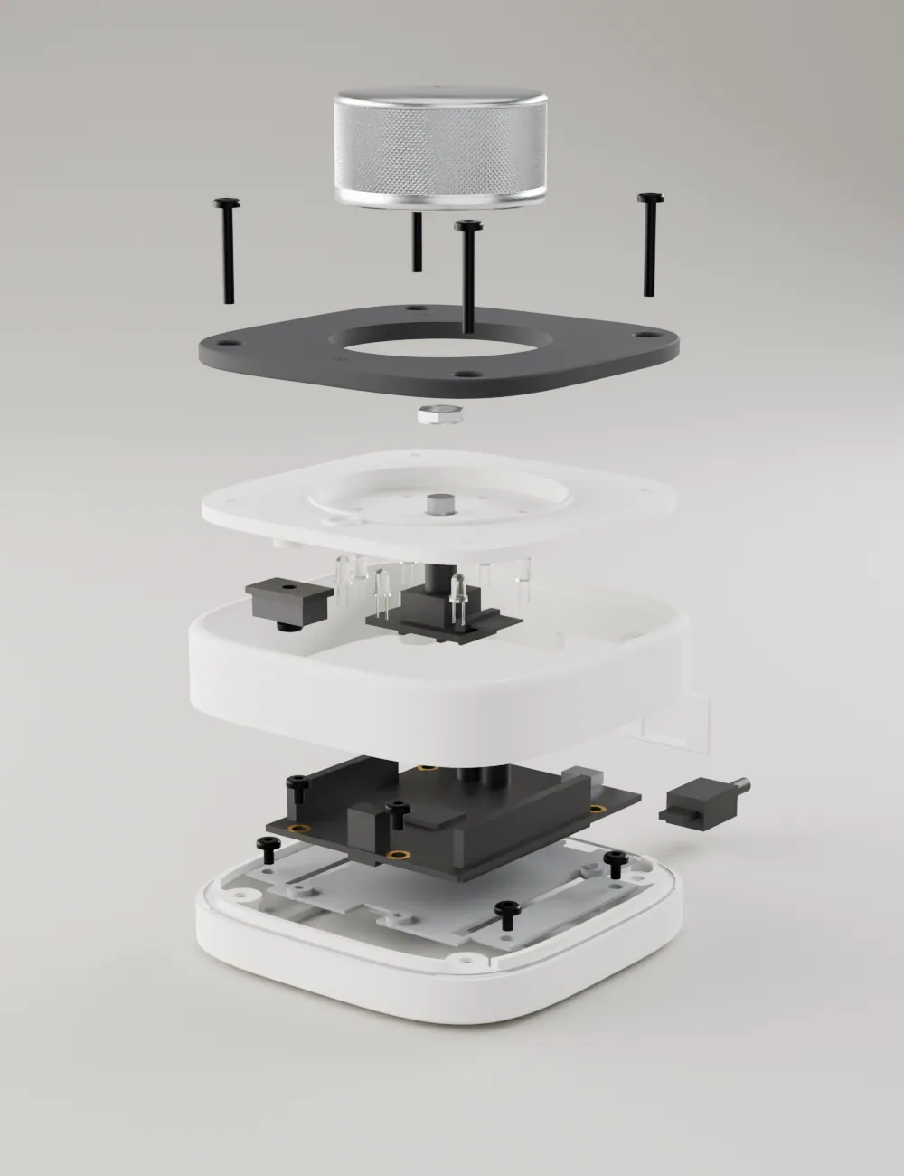
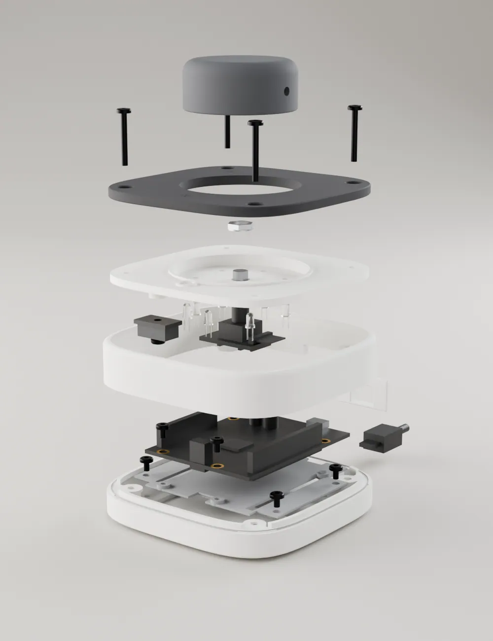
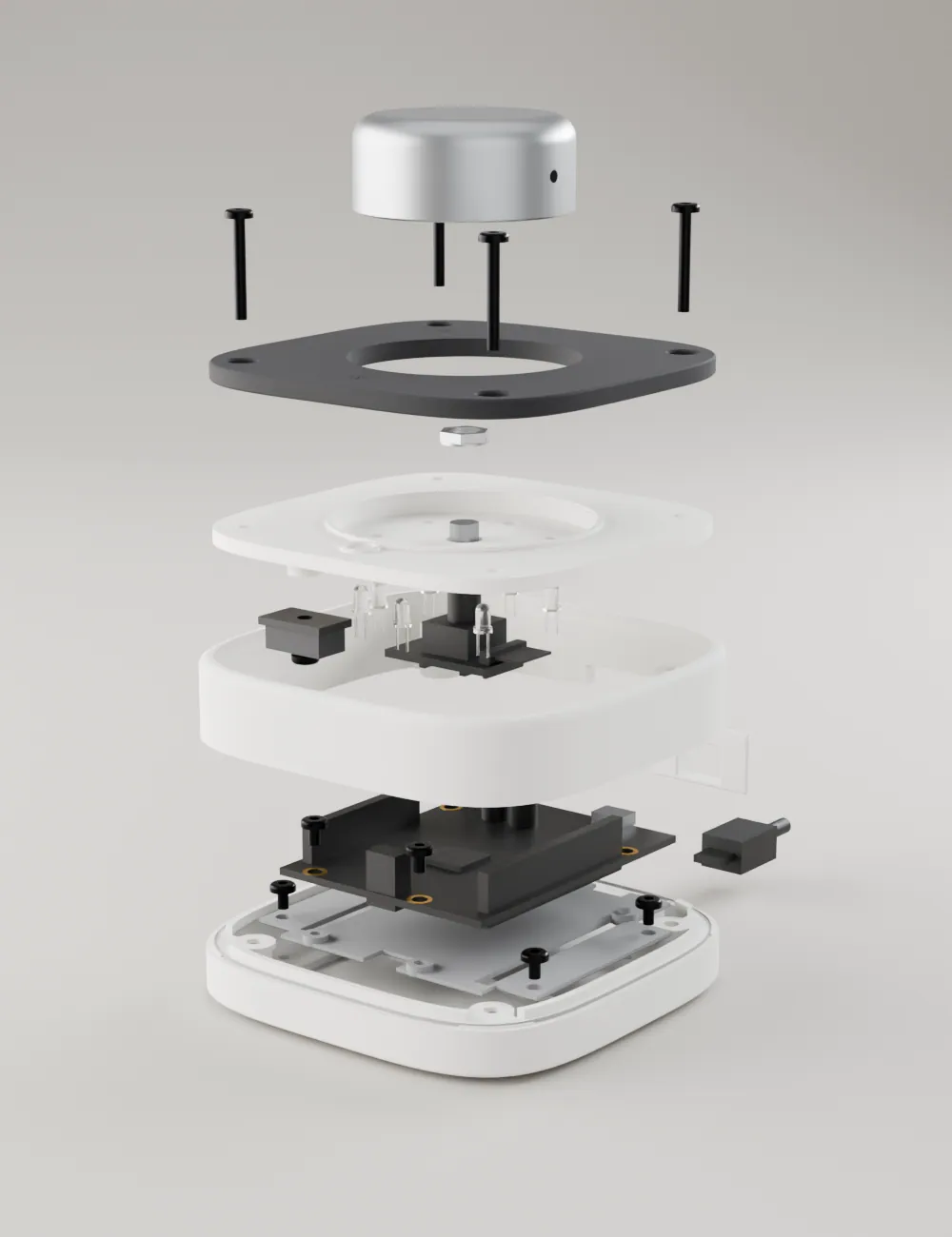
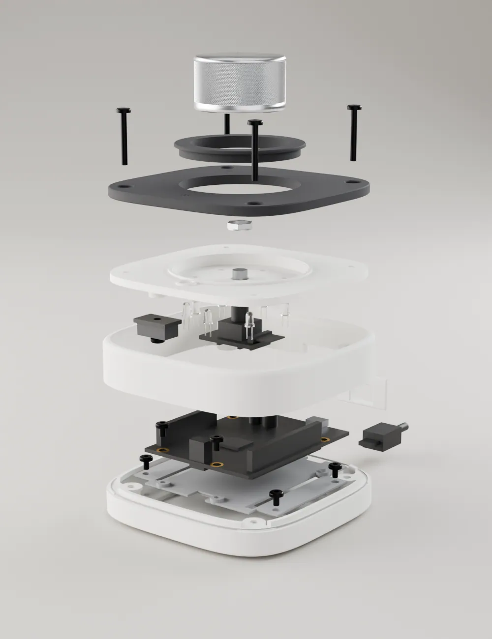
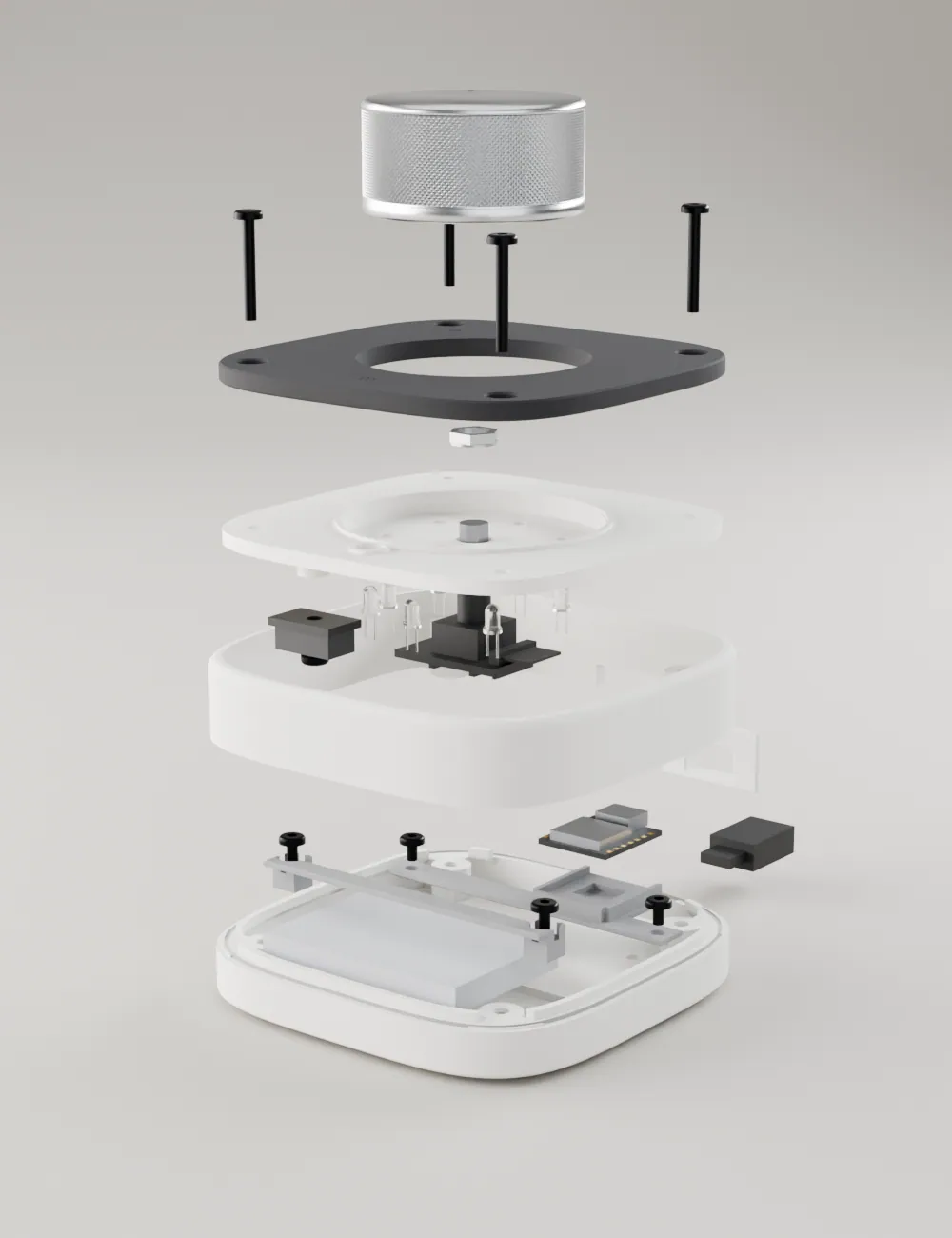
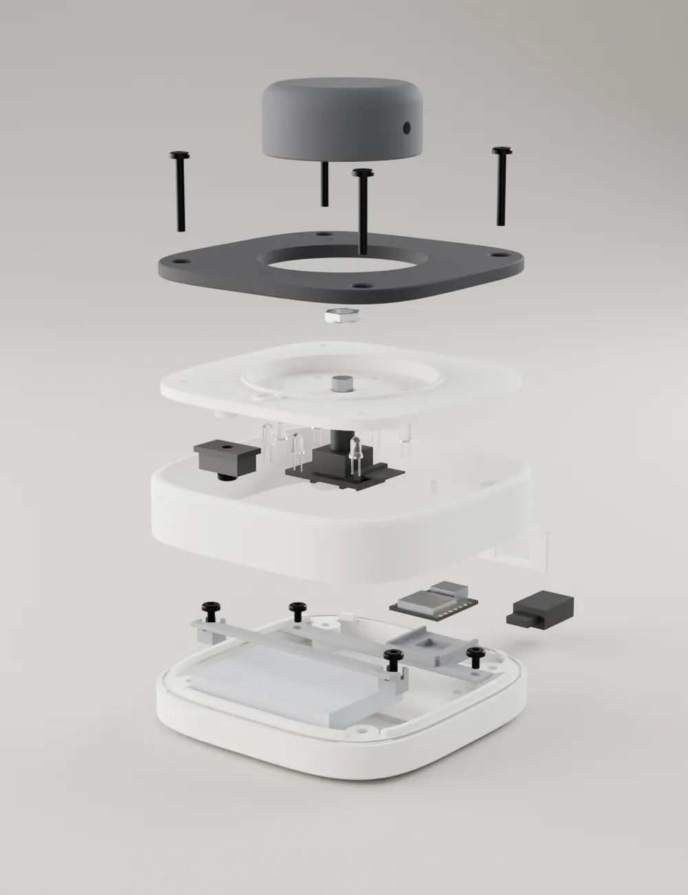
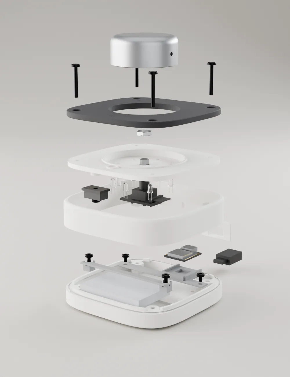
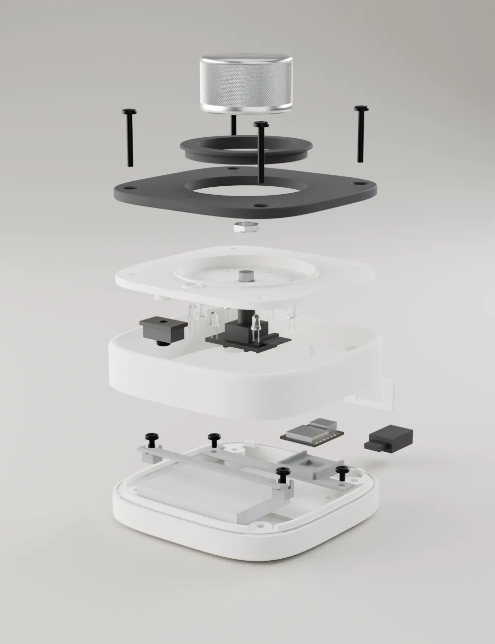
Callouts
FIG. 5- Lower body, 1 to 4
- 01Face nuts4 x M3 nut
- 02Tray4 x M3 x 4
- 03Arduino Leonardo2 x M3 x 4
- 04Port plateprinted
- Light deck, on the bench, 5 to 8
- 05EncoderKY-040
- 06Washer and M7 nutwith the encoder
- 07LEDs6 halo + 1 dot
- 08Driver perfboard1 x M3 x 6
- Close up, 9 to 14
- 09Upper bodyprinted
- 10Light decksteps 5 to 8
- 11Face panelprinted
- 12Face screws4 x M3 x 20
- 13Knobgrub screw
- 14Feet4 bumpers
- Lower body, 1 to 5
- 01Face nuts4 x M3 nut
- 02Battery and strap2 x M3 x 6
- 03XIAO tray2 x M3 x 4
- 04XIAO nRF52840XIAO nRF52840
- 05Port plateprinted, USB-C
- Light deck, on the bench, 6 to 9
- 06EncoderKY-040
- 07Washer and M7 nutwith the encoder
- 08LEDs6 halo + 1 dot
- 09Driver perfboard1 x M3 x 6
- Close up, 10 to 15
- 10Upper bodyprinted
- 11Light decksteps 6 to 9
- 12Face panelprinted
- 13Face screws4 x M3 x 20
- 14Knobgrub screw
- 15Feet4 bumpers
-
USB edition
-
01
Press in the face nuts
Lower body, 4 x M3 nut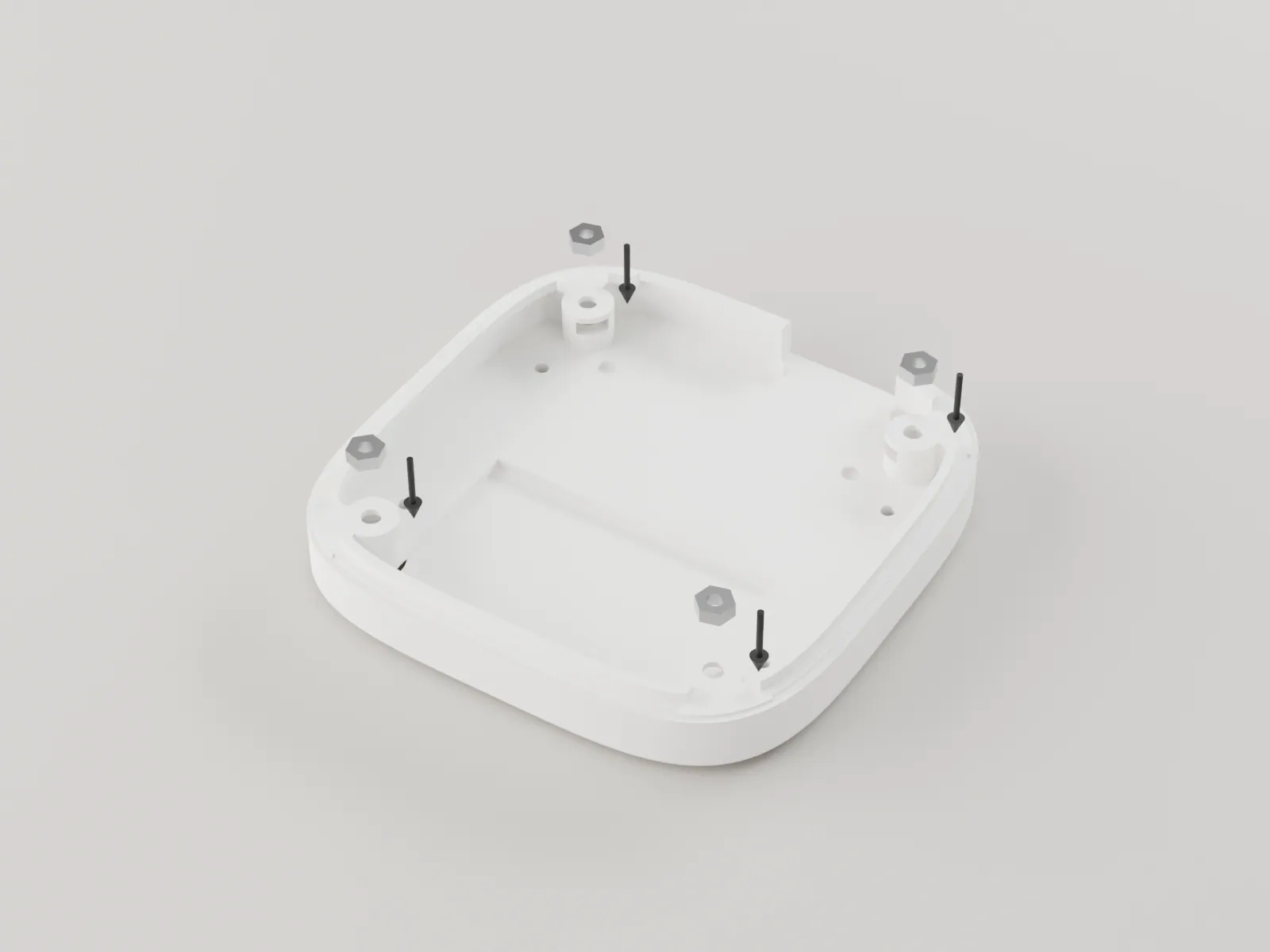
Drop an M3 nut into each of the four hex pockets in the corner bosses, from inside the lower body. Press each one down flat with the tip of a screwdriver.
Each nut sits flat at the bottom of its pocket and cannot spin. A nut that sits proud stops the face screw reaching it.
-
02
Screw down the tray
Leonardo tray, 4 x M3 x 4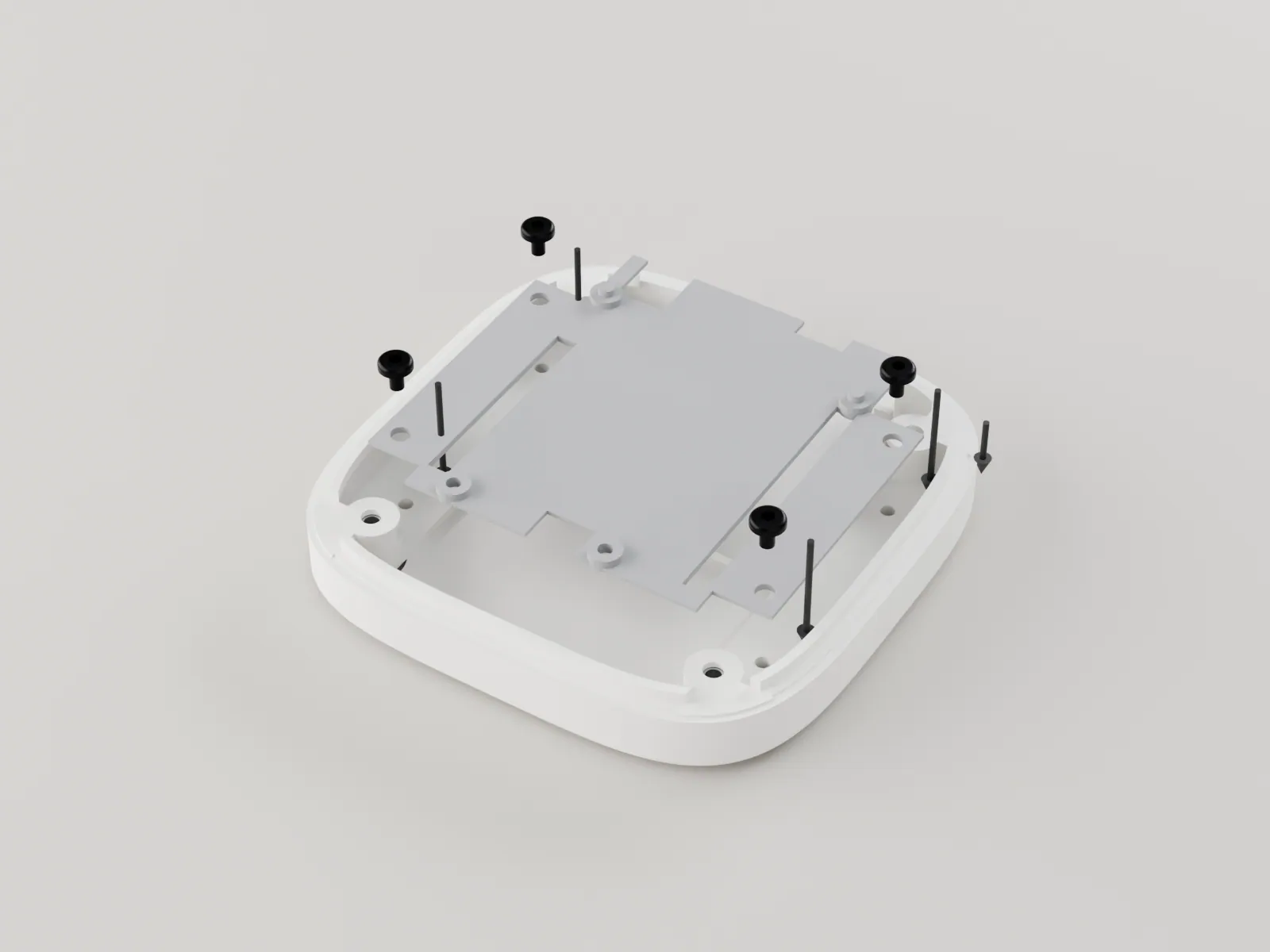
Lay the tray on the floor, its two round locating pins towards the back, over the four tapped holes. Drive an M3 x 4 button head through each corner into the floor.
The tray sits flat and does not rock. Snug the screws only: the threads are cut in resin.
-
03
Fit the Leonardo
Arduino Leonardo, wired, 2 x M3 x 4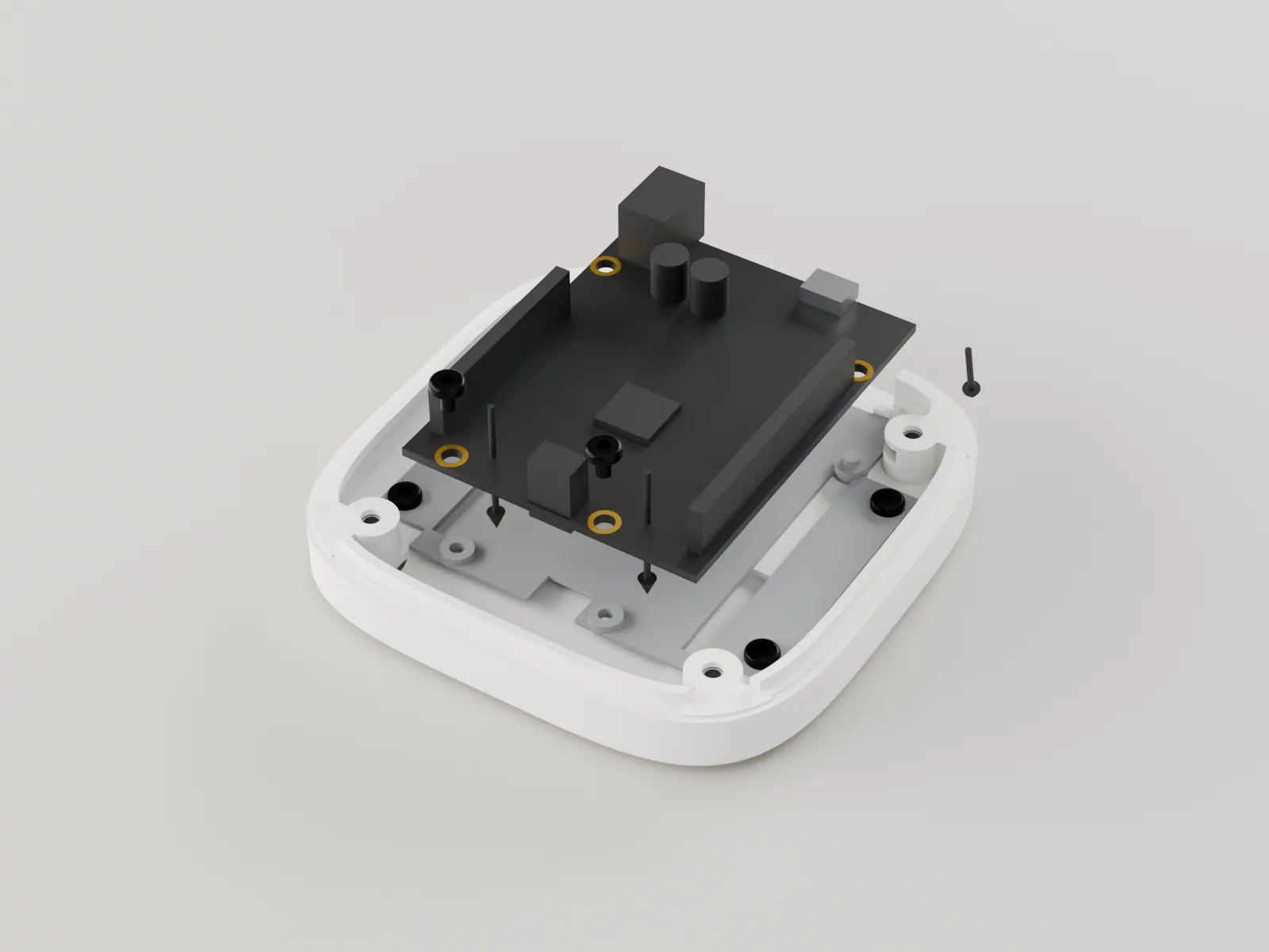
Turn the board so its USB edge faces the back. Lower it so the two holes by the barrel jack and the digital header drop over the tray's pins, then fit two M3 x 4 screws in the two holes at the far end. Plug in the harness.
The micro-USB socket lines up with the notch in the back wall.
-
04
Fit the port plate
Micro-USB port plate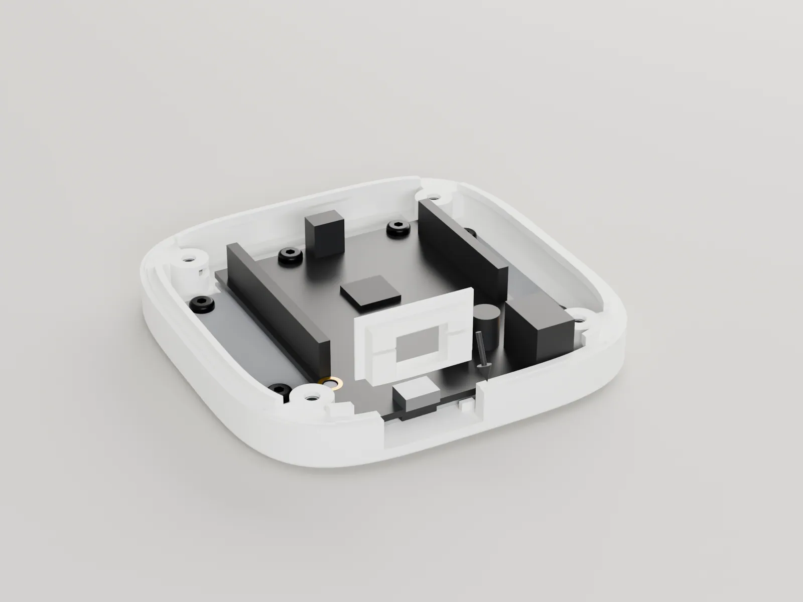
From inside, set the port plate into the notch at the back of the lower body: flange inside, chamfered lip facing out. The upper body will trap it in step 9.
A micro-USB plug goes straight through the plate into the socket without touching the lip.
-
05
Seat the encoder
Light deck, KY-040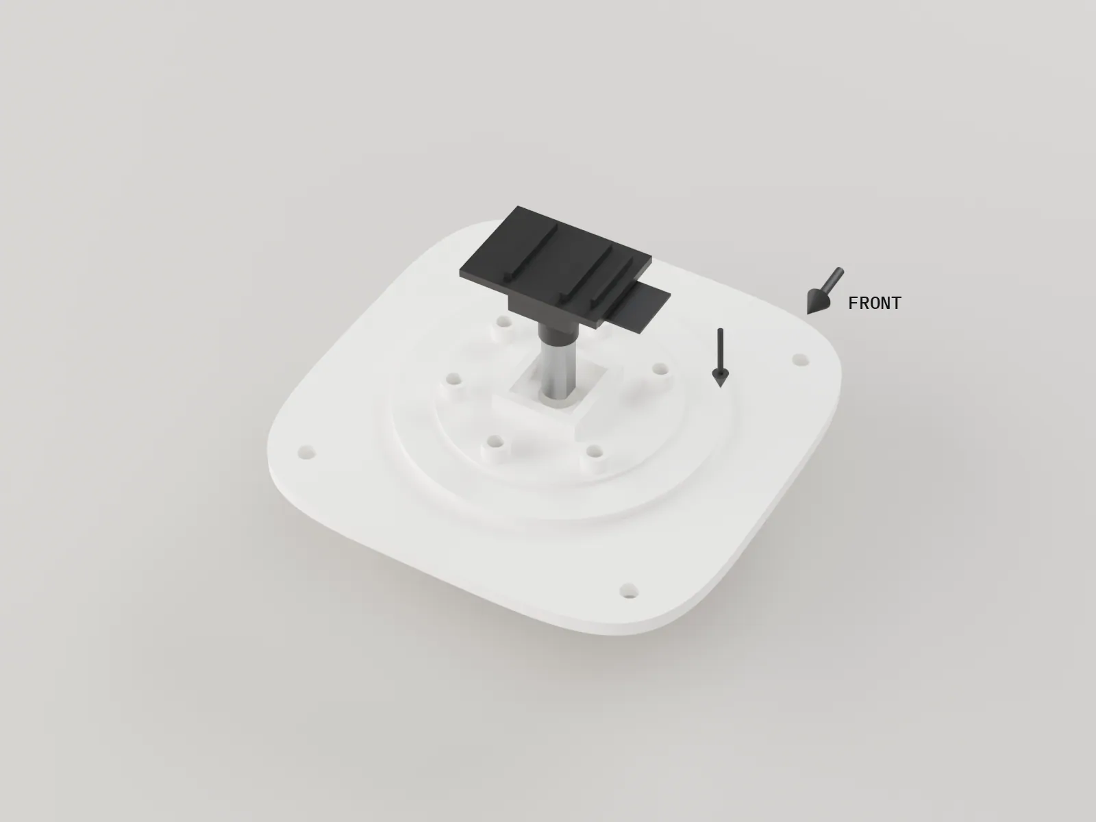
Turn the light deck upside down. Push the encoder's threaded collar through the centre hole until its can sits fully in the square skirt, with its header pins towards the right-hand side of the device, between two LED tubes.
The can sits square in the skirt and cannot turn.
-
06
Clamp it with the nut
M7 washer and nut, from the encoder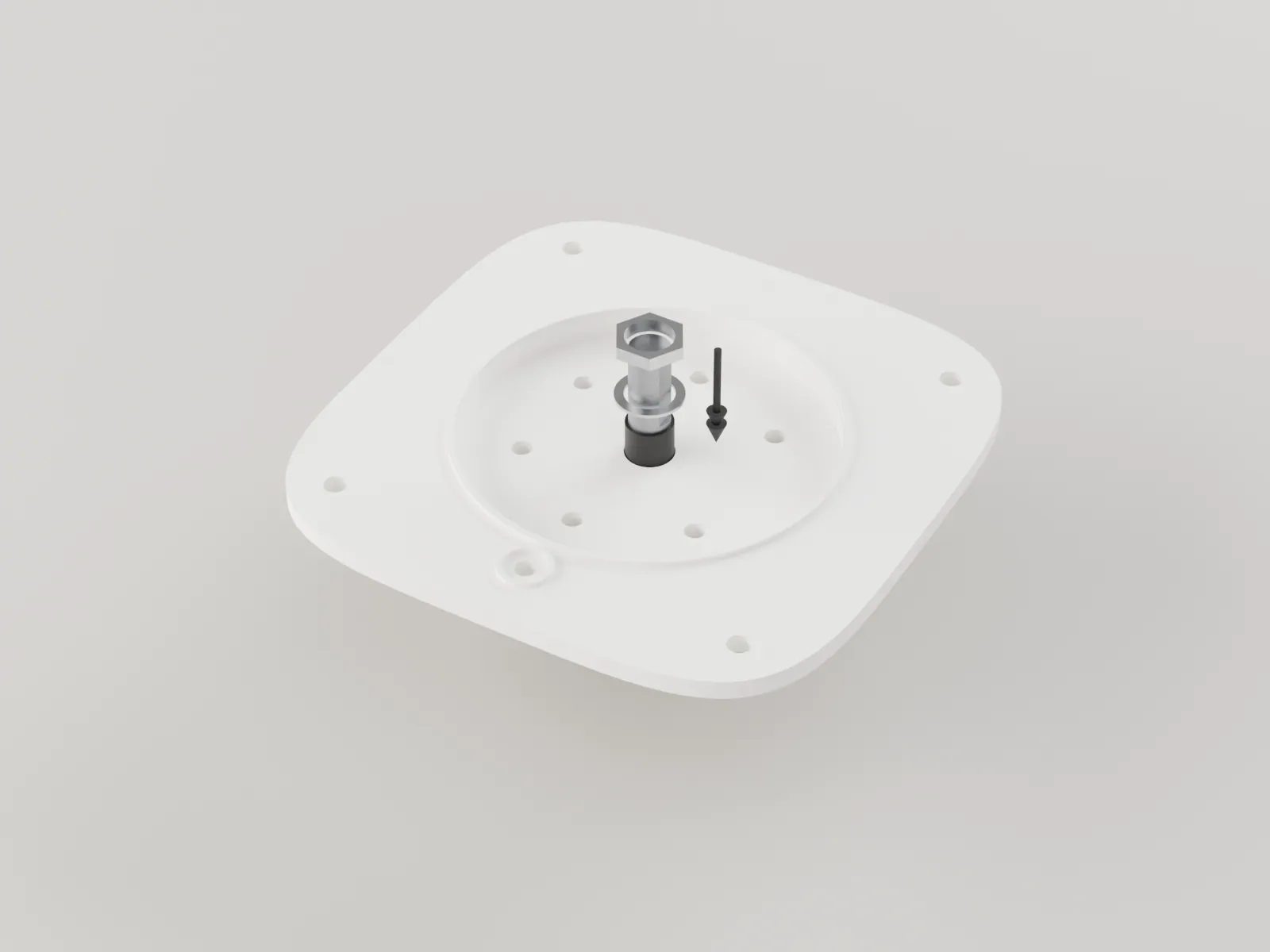
Turn the deck the right way up. Fit the washer, then the M7 nut, on the collar and tighten the nut firmly with a small spanner. Firm, not forced: the web under it is resin.
The encoder does not rock or turn when you twist the shaft hard both ways.
-
07
Fit the LEDs
6 halo LEDs, 1 dot LED, wired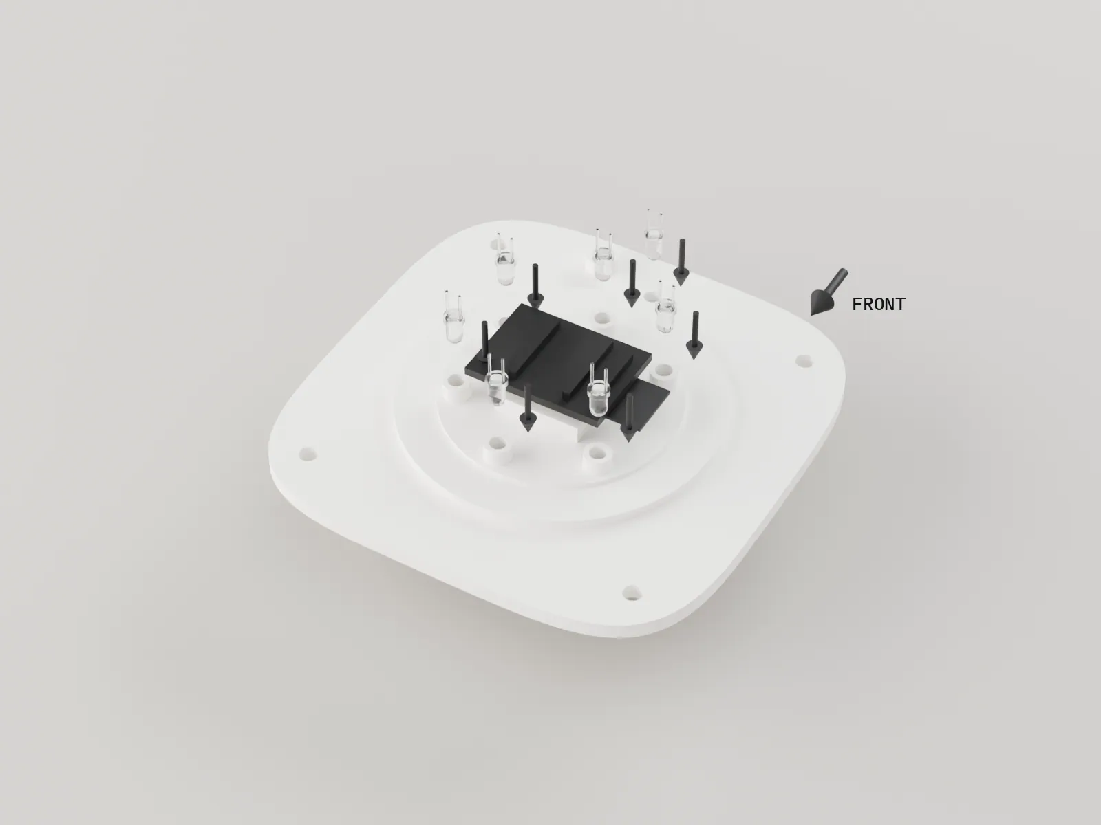
Deck upside down again. Push each halo LED into its tube until its flange stops. Push the dot LED into the bore under the dot, at the front edge of the deck.
Every flange is home and no LED dome stands above the moat floor.
-
08
Fit the driver board
Driver perfboard, 1 x M3 x 6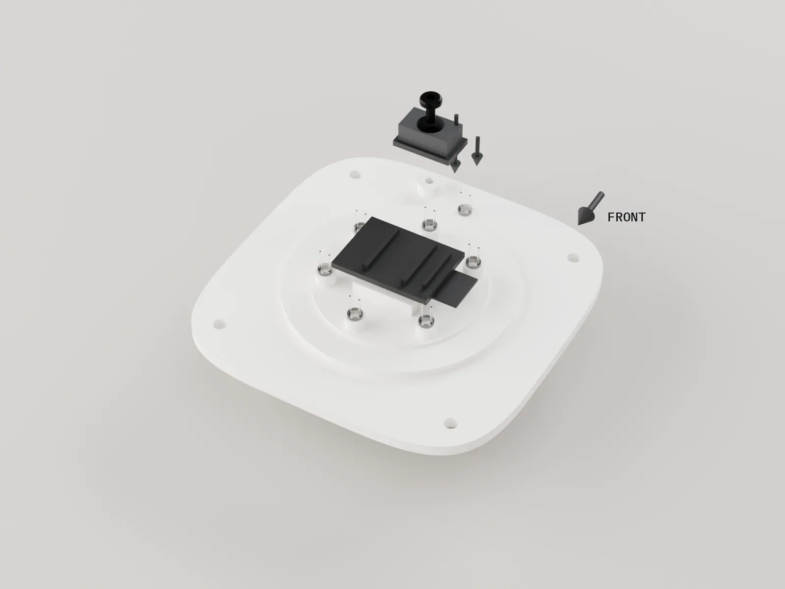
Screw the 16 x 10 mm driver perfboard to the boss under the deck, at the front left of the device, with one M3 x 6. Dress the wires flat under the deck.
No bare lead touches another, and no wire crosses an LED tube mouth.
-
09
Set on the upper body
Upper body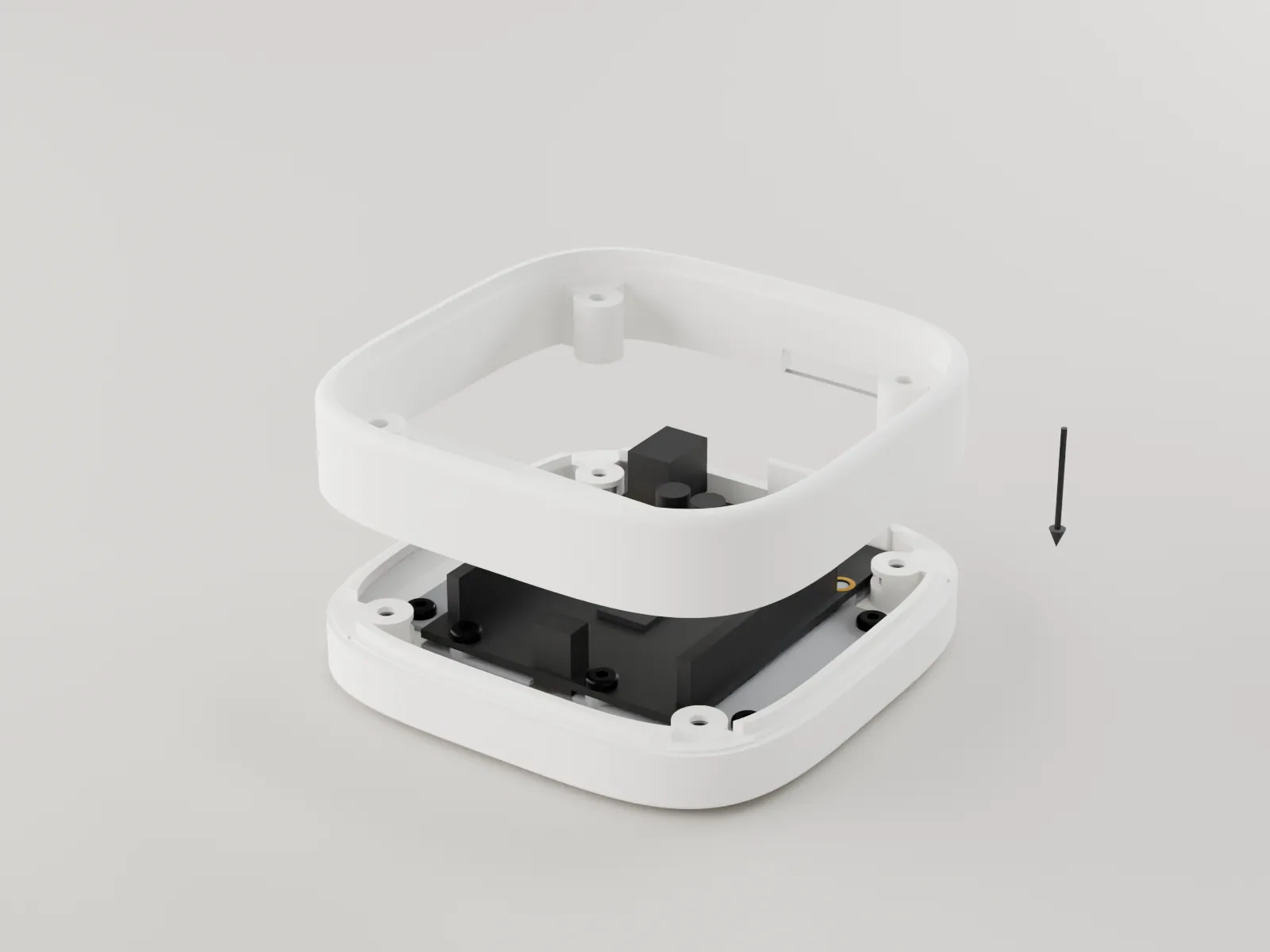
Hold the wired deck to one side and lower the upper body onto the lower body, passing the deck's wires up through it. The register lip drops inside, and the port plate is caught between the two halves.
The dark groove is even all round. If one side gapes, a wire or the port plate is caught.
-
10
Drop in the light deck
Deck from steps 5 to 8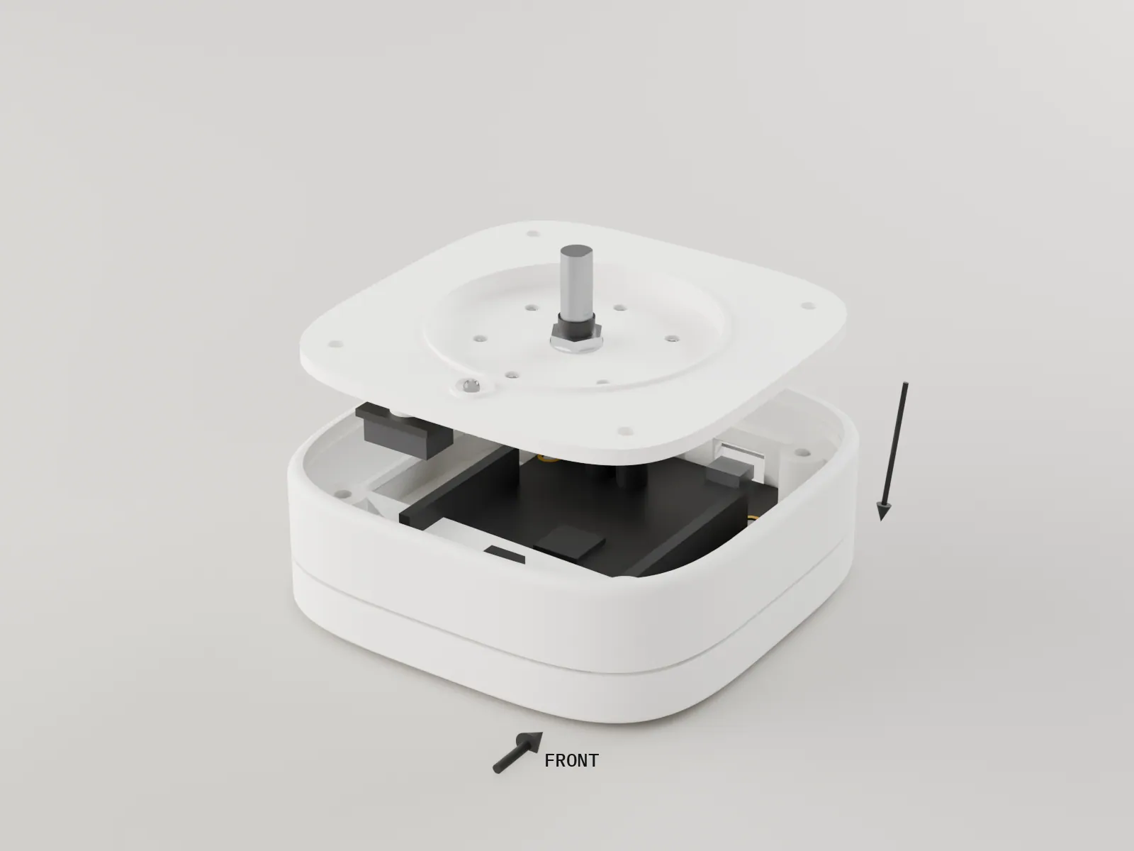
Fold the wires down into the body and lower the deck in, light-seal tongues up, the dot LED at the front. It rests on the four corner columns.
The deck sits level, with no wire trapped under its edge, and the dot LED is at the front, opposite the USB.
-
11
Lay on the face panel
Face panel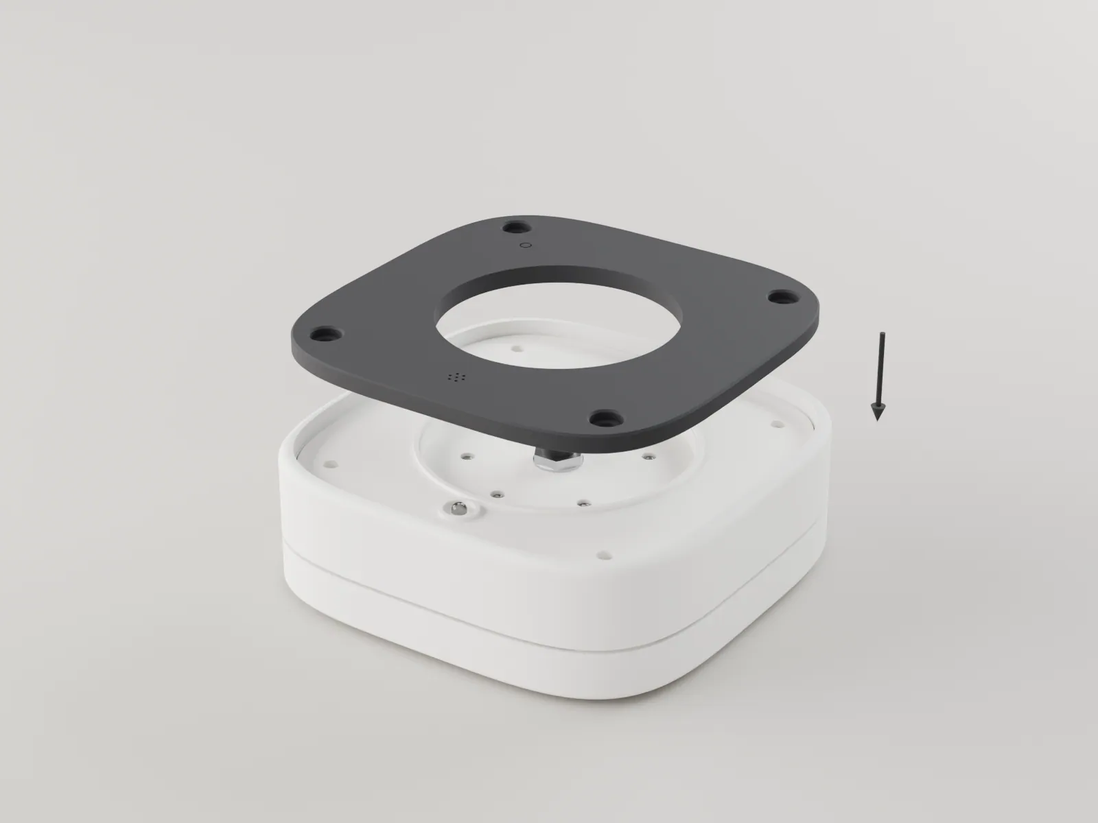
Lay the panel on with the seven dot holes at the front. Its grooves take the deck's tongues; press it down evenly until it sits flat.
The panel stands 0.6 mm proud of the rim with an even shadow gap on all four sides.
-
12
Drive the face screws
4 x M3 x 20 button head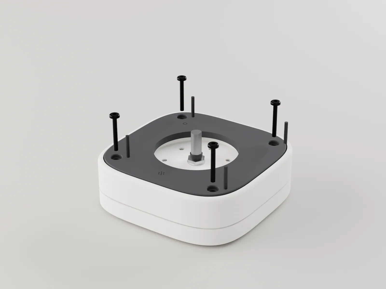
Drive the four M3 x 20 screws through the panel corners into the captive nuts. Turn each a few turns at a time, corner to opposite corner, until snug.
The heads sit just below the panel face. Stop at snug: more bows the panel and opens the light seals.
-
13
Fit the knob
Knob, its grub screw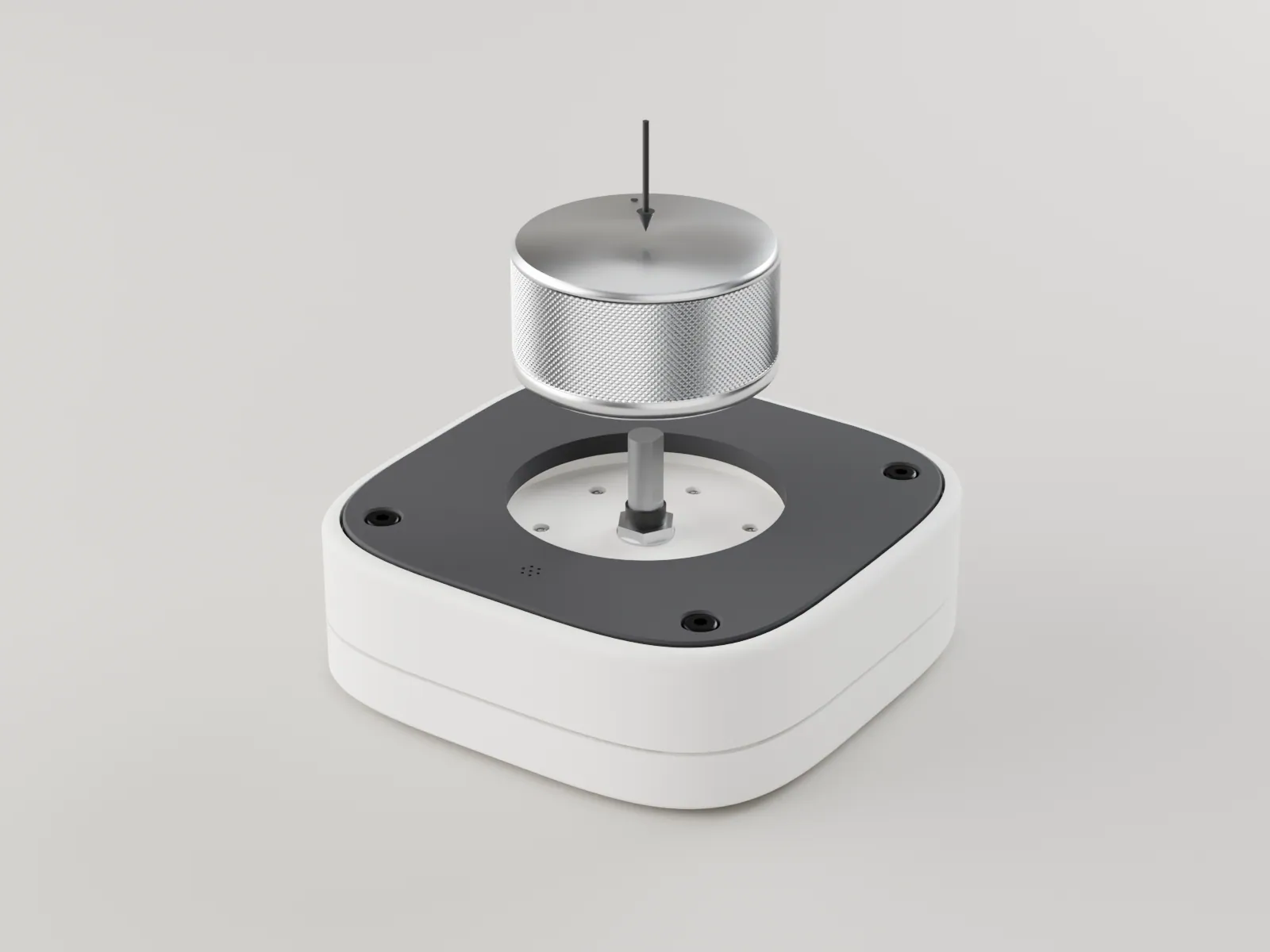
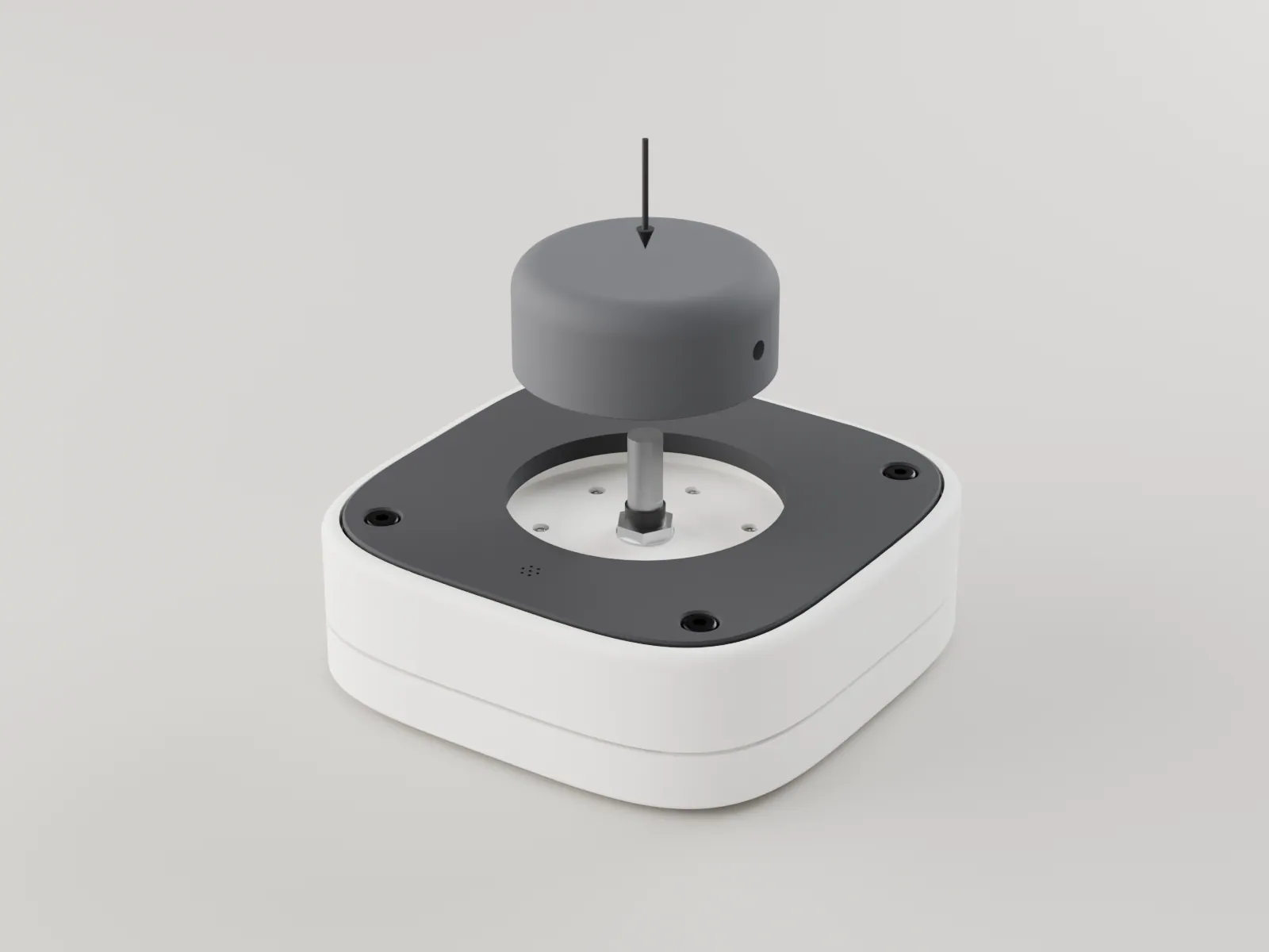
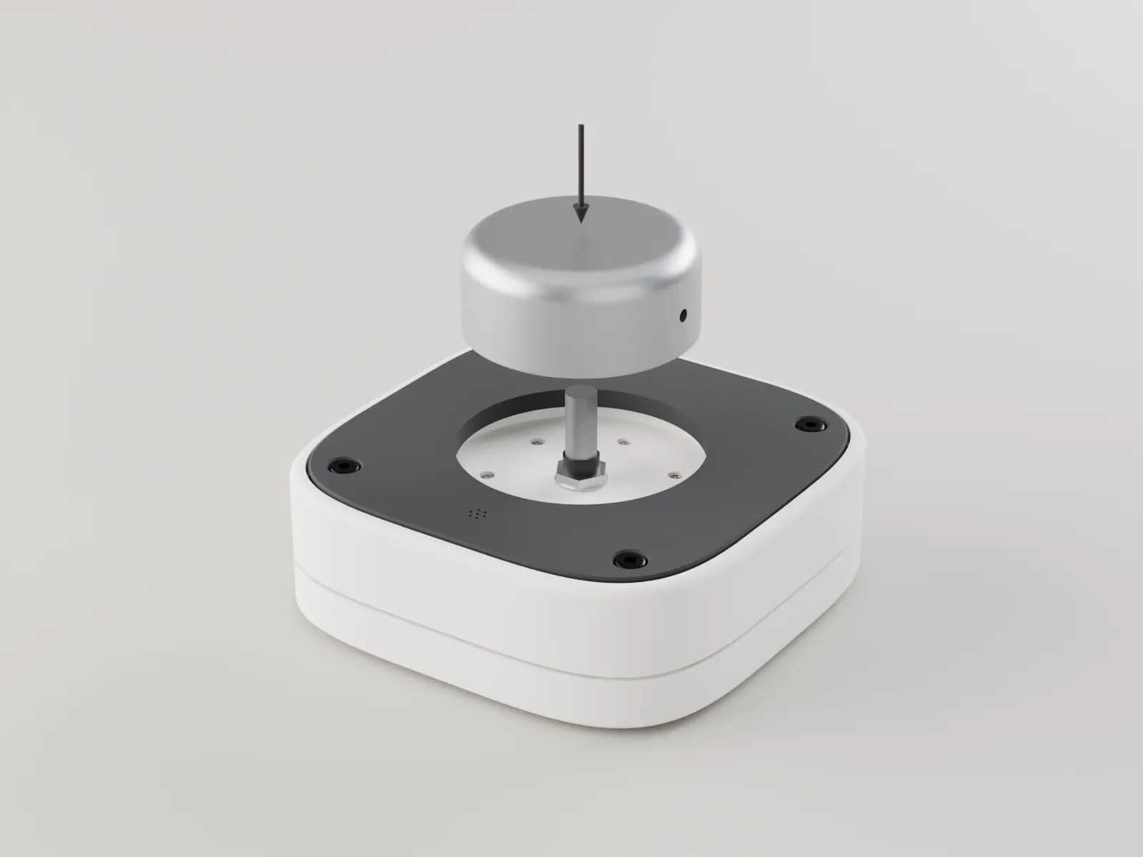
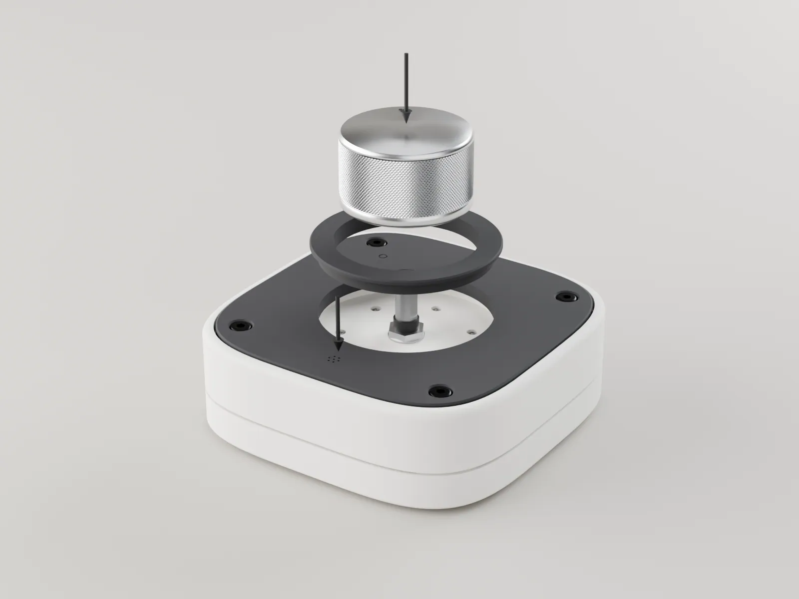
Turn the shaft so its D flat faces you. Turn the knob so its grub screw faces you too, push it down onto the shaft until it seats over the nut, and tighten the grub screw onto the flat.
Printed Budget knob: the M3 nut is already in its trap and the washer glued in (section 06). After it seats, run the M3 x 6 grub screw in from the side through the nut and tighten it onto the flat. Stop at snug. Premium CNC knob: the same, with the grub screw in the tapped hole.
Your own knob with a ring adapter: first drop the ring's plug into the deck opening so its flange lies on the panel face, fixed with a dab of glue or double-sided tape under the flange. Then fit your knob as above.
The knob turns freely without touching the moat floor, and a press clicks cleanly. If it will not seat, the flat is too short (section 04). With a ring adapter, the gap round the knob is even and the knob's base does not touch the ring.
-
14
Stick on the feet
4 adhesive bumpers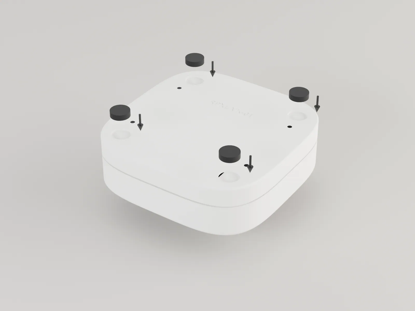
Turn the unit over onto a soft cloth. Press a bumper into each of the four recesses under the corners.
It sits on all four feet without rocking.
-
Bluetooth edition
-
01
Press in the face nuts
Lower body, 4 x M3 nut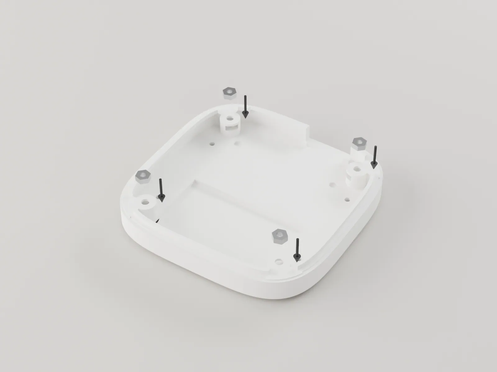
Drop an M3 nut into each of the four hex pockets in the corner bosses, from inside the lower body. Press each one down flat with the tip of a screwdriver.
Each nut sits flat at the bottom of its pocket and cannot spin. A nut that sits proud stops the face screw reaching it.
-
02
Strap in the battery
LiPo cell, battery strap, 2 x M3 x 6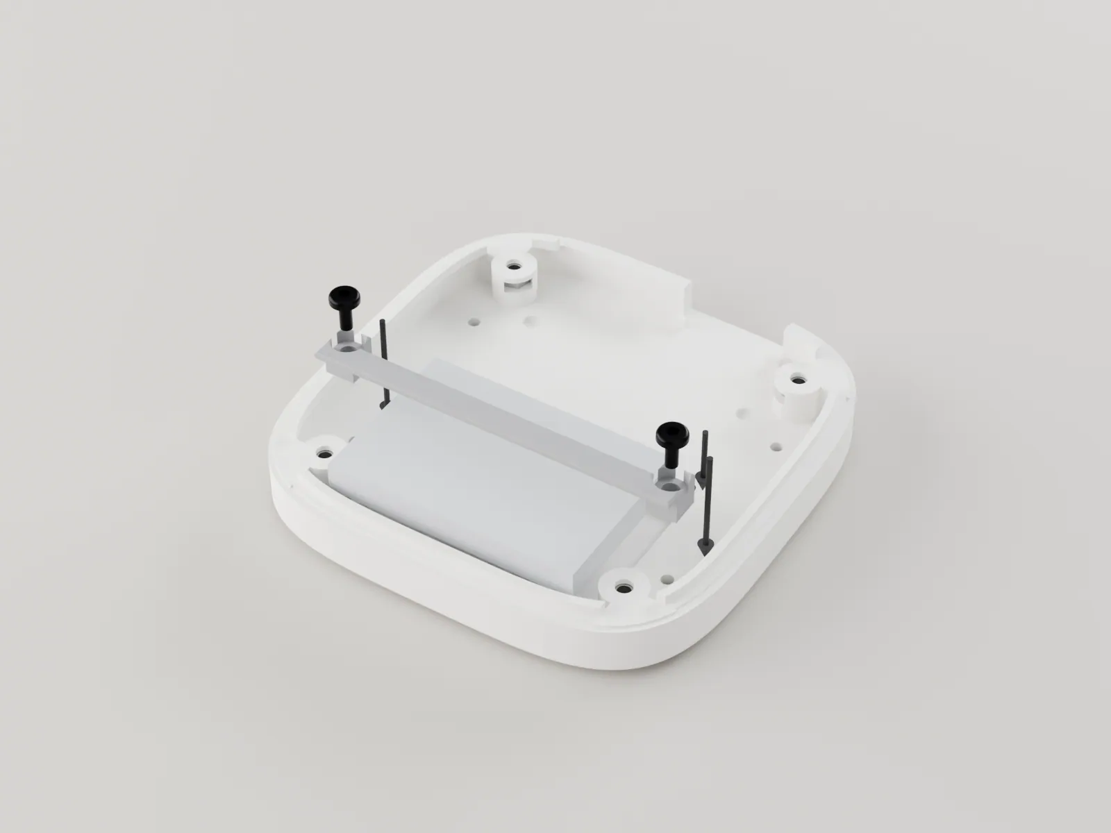
Lay the cell in the pocket at the front of the floor with a thin layer of foam on each face, its lead towards the board. Hold it with the printed strap, laid across the cell, and two M3 x 6 screws into the two front tapped floor holes.
The cell cannot slide, the strap lies flat across it and the screws are snug.
-
03
Screw down the tray
XIAO tray, 2 x M3 x 4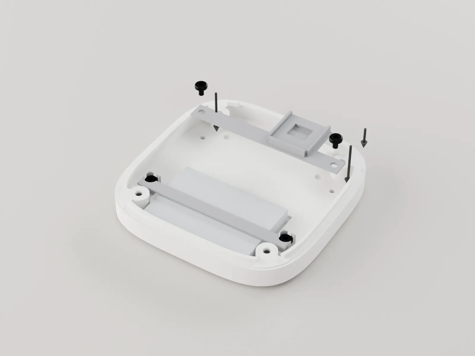
Lay the tray on the floor over the two back tapped holes, the ones the strap does not use, and drive an M3 x 4 button head through each into the floor.
The tray sits flat and does not rock. Snug the screws only: the threads are cut in resin.
-
04
Fit the XIAO
Seeed XIAO nRF52840, wired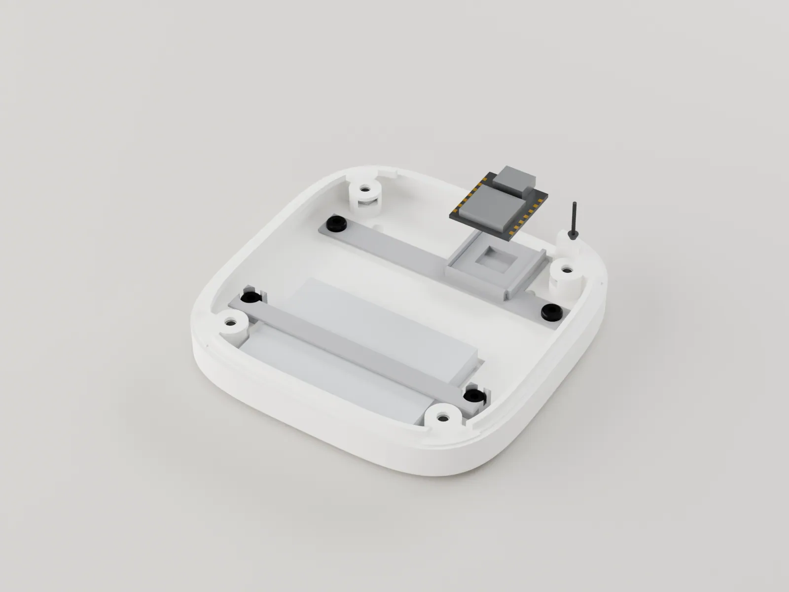
Turn the board so its USB-C end faces the back. Pass the cell's leads through the slot in the tray, then lower the XIAO between the side guides onto the raised pad until its front edge meets the front stop. The harness wires are already soldered to it, and it needs no screw.
The USB-C socket lines up with the notch in the back wall.
-
05
Fit the port plate
USB-C port plate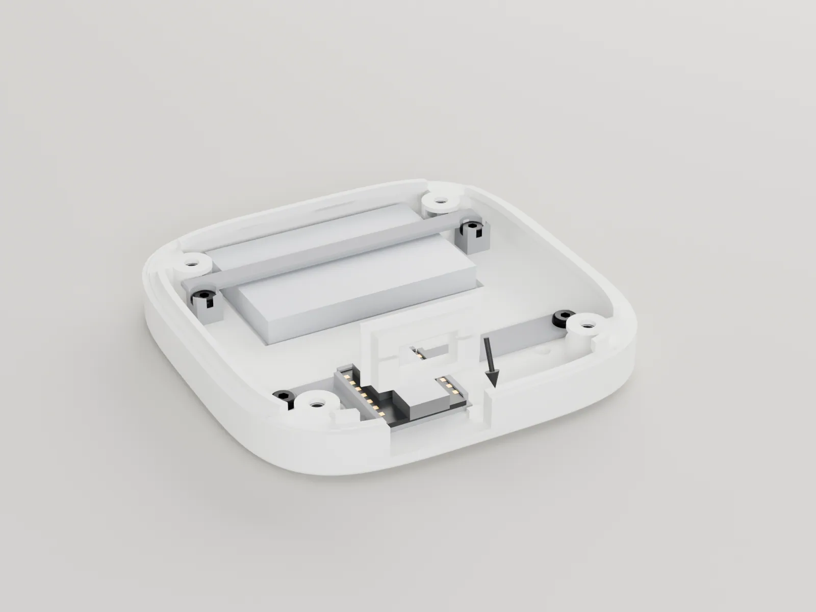
From inside, set the USB-C port plate into the notch at the back of the lower body: flange inside, chamfered lip facing out. It frames the XIAO's own USB-C socket. The upper body will trap it in step 10.
A USB-C plug goes straight through the plate into the socket without touching the lip.
-
06
Seat the encoder
Light deck, KY-040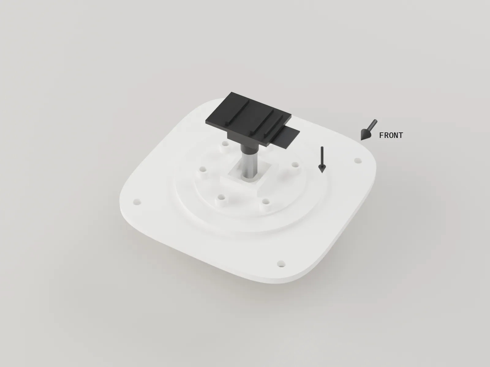
Turn the light deck upside down. Push the encoder's threaded collar through the centre hole until its can sits fully in the square skirt, with its header pins towards the right-hand side of the device, between two LED tubes.
The can sits square in the skirt and cannot turn.
-
07
Clamp it with the nut
M7 washer and nut, from the encoder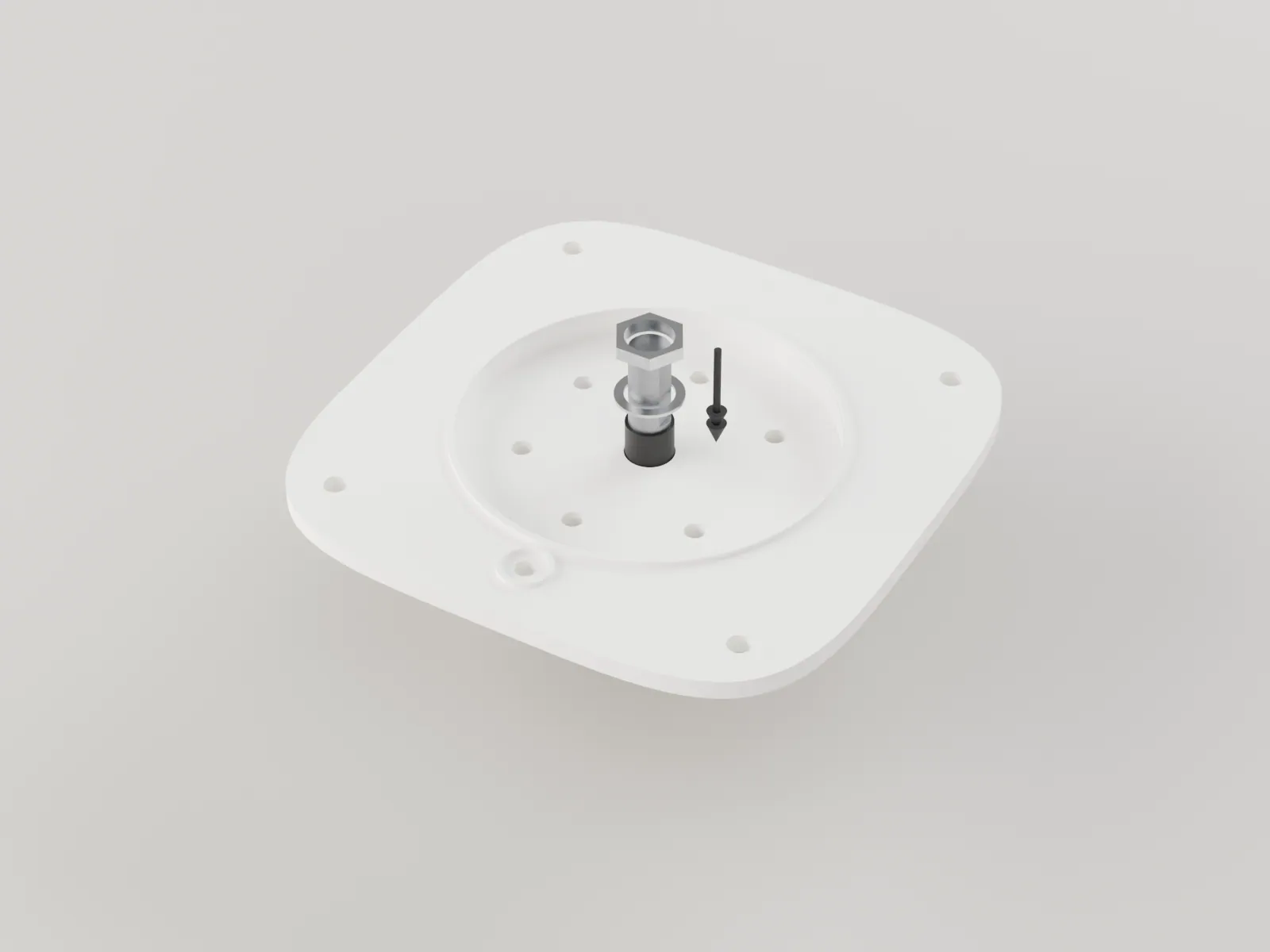
Turn the deck the right way up. Fit the washer, then the M7 nut, on the collar and tighten the nut firmly with a small spanner. Firm, not forced: the web under it is resin.
The encoder does not rock or turn when you twist the shaft hard both ways.
-
08
Fit the LEDs
6 halo LEDs, 1 dot LED, wired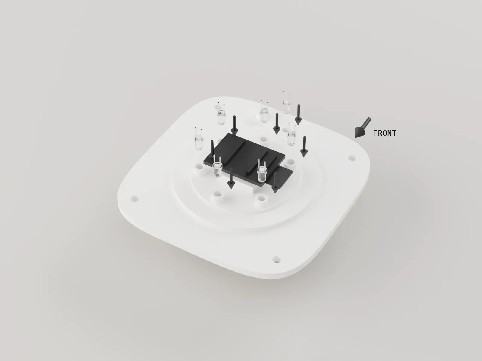
Deck upside down again. Push each halo LED into its tube until its flange stops. Push the dot LED into the bore under the dot, at the front edge of the deck.
Every flange is home and no LED dome stands above the moat floor.
-
09
Fit the driver board
Driver perfboard, 1 x M3 x 6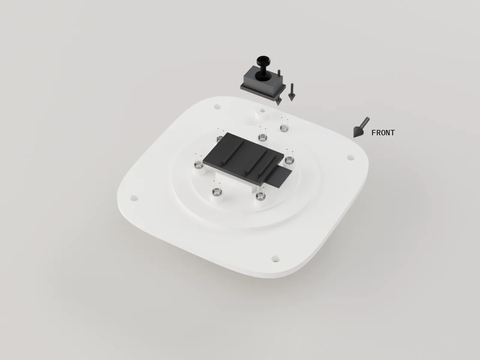
Screw the 16 x 10 mm driver perfboard to the boss under the deck, at the front left of the device, with one M3 x 6. Dress the wires flat under the deck.
No bare lead touches another, and no wire crosses an LED tube mouth.
-
10
Set on the upper body
Upper body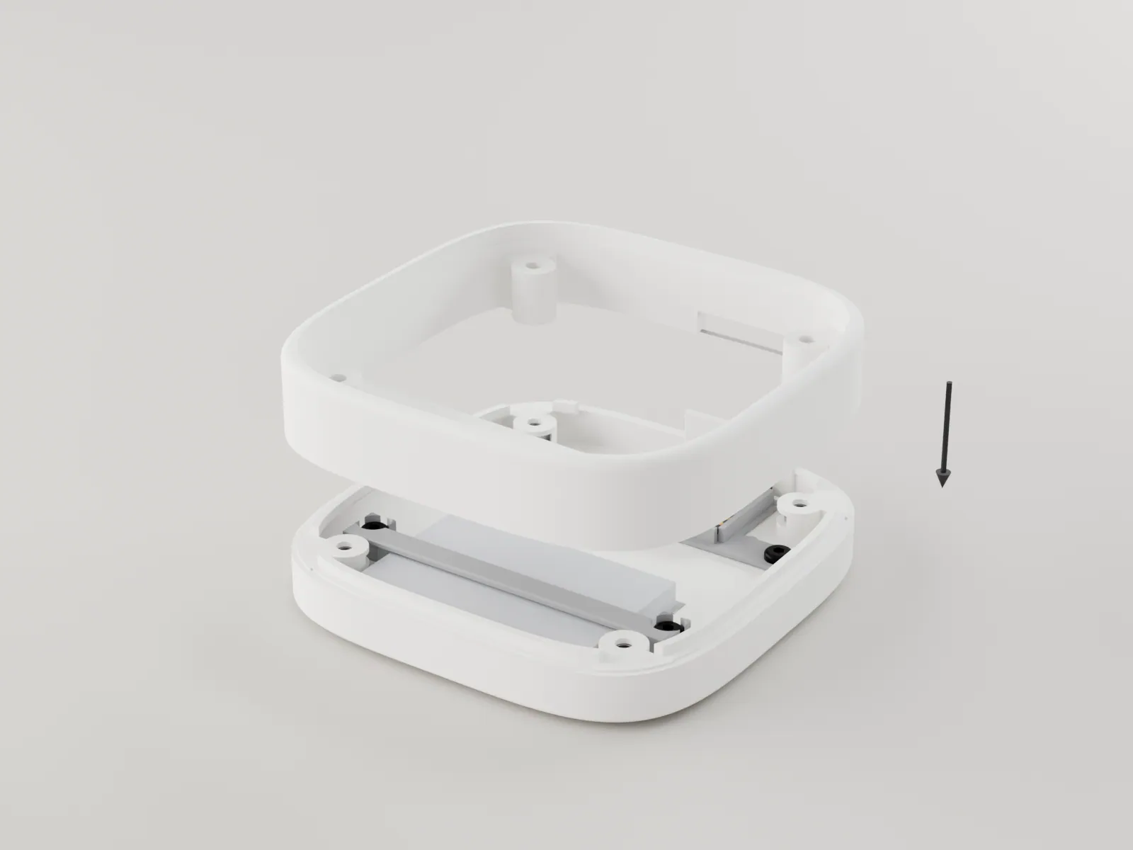
Hold the wired deck to one side and lower the upper body onto the lower body, passing the deck's wires up through it. The register lip drops inside, and the port plate is caught between the two halves.
The dark groove is even all round. If one side gapes, a wire or the port plate is caught.
-
11
Drop in the light deck
Deck from steps 6 to 9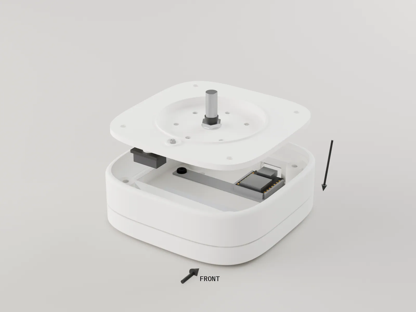
Fold the wires down into the body and lower the deck in, light-seal tongues up, the dot LED at the front. It rests on the four corner columns.
The deck sits level, with no wire trapped under its edge, and the dot LED is at the front, opposite the USB-C port.
-
12
Lay on the face panel
Face panel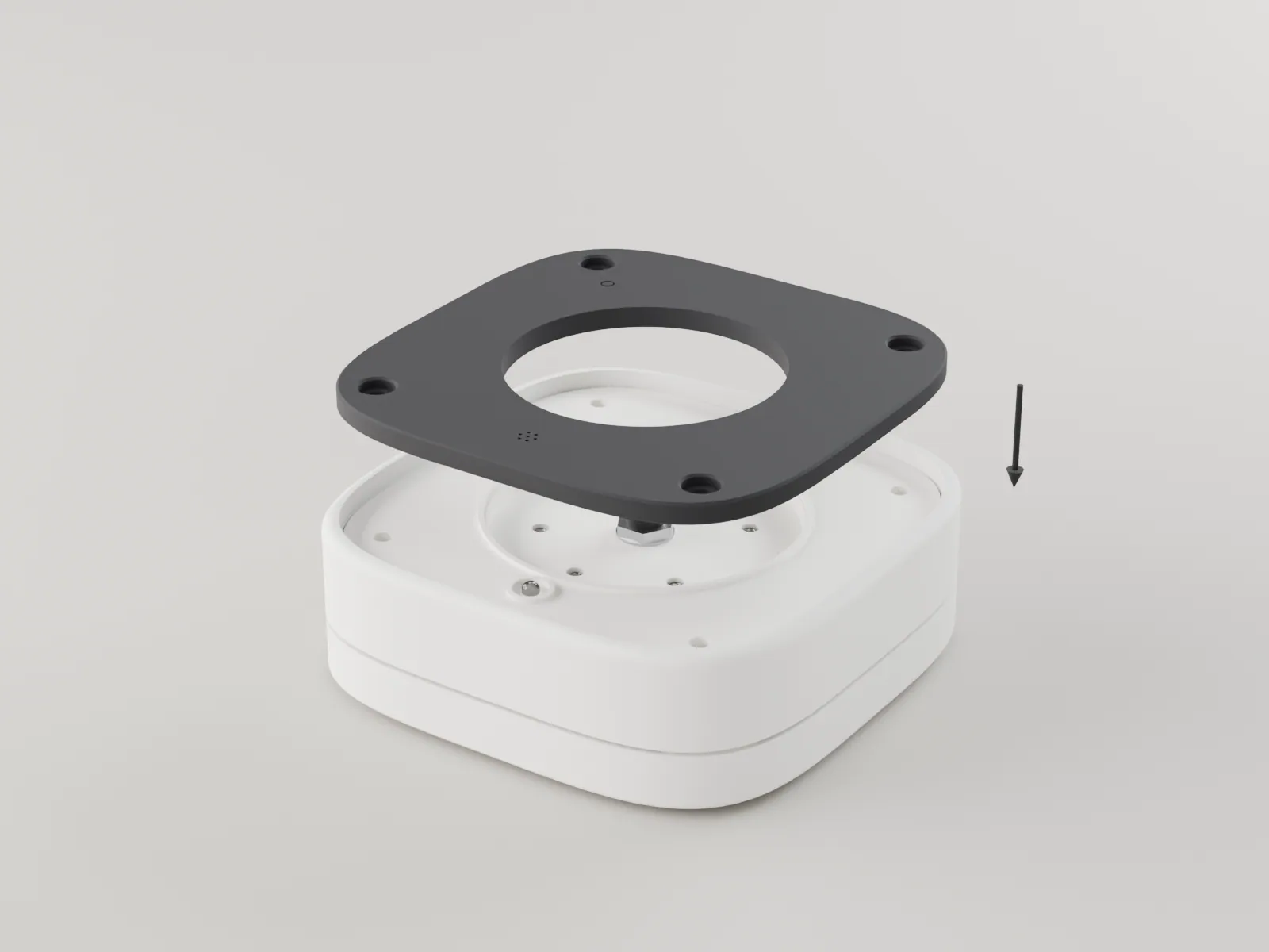
Lay the panel on with the seven dot holes at the front. Its grooves take the deck's tongues; press it down evenly until it sits flat.
The panel stands 0.6 mm proud of the rim with an even shadow gap on all four sides.
-
13
Drive the face screws
4 x M3 x 20 button head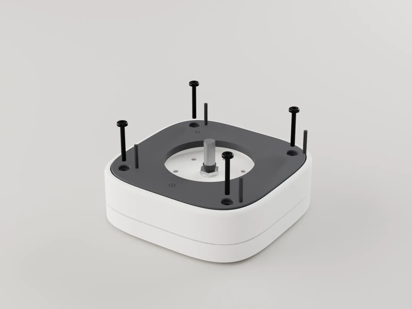
Drive the four M3 x 20 screws through the panel corners into the captive nuts. Turn each a few turns at a time, corner to opposite corner, until snug.
The heads sit just below the panel face. Stop at snug: more bows the panel and opens the light seals.
-
14
Fit the knob
Knob, its grub screw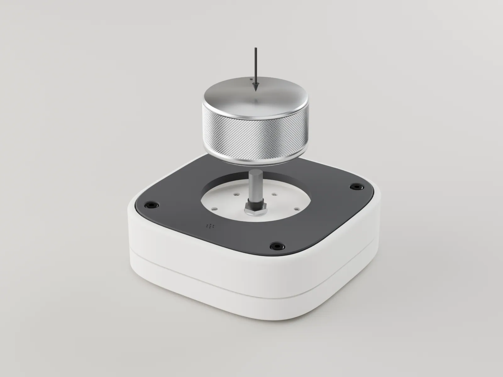
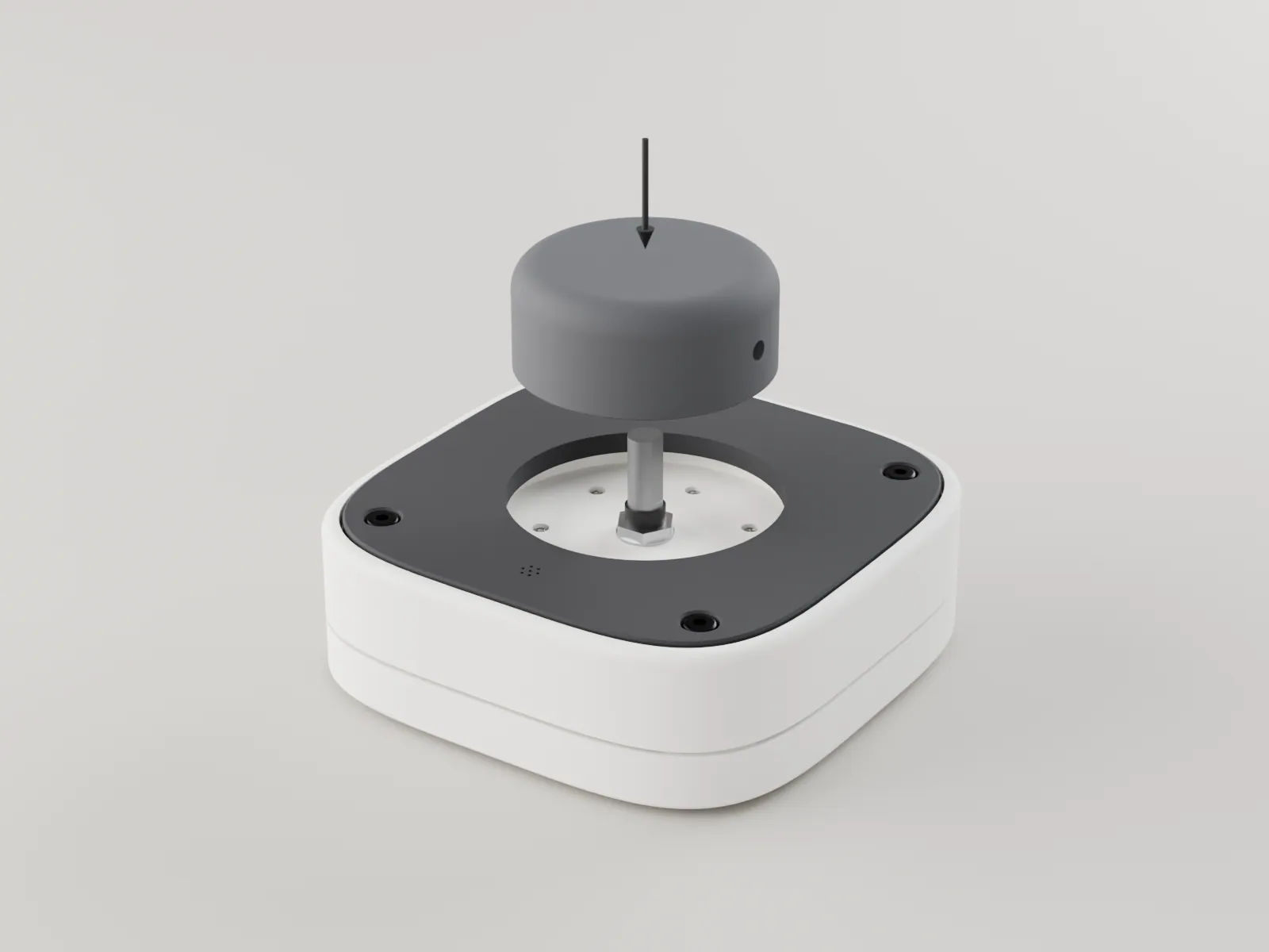
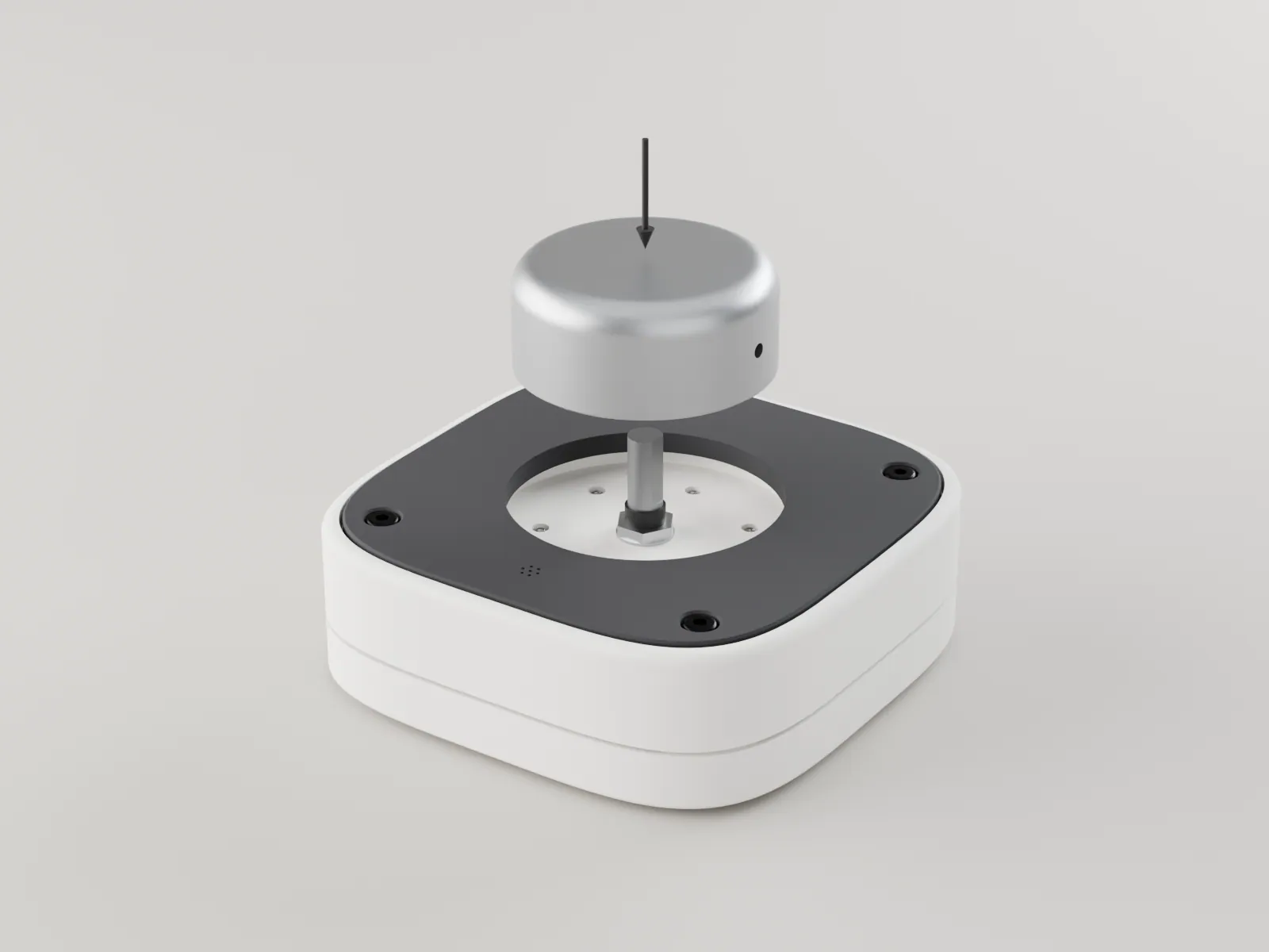
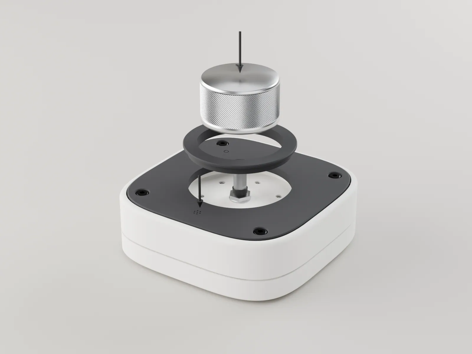
Turn the shaft so its D flat faces you. Turn the knob so its grub screw faces you too, push it down onto the shaft until it seats over the nut, and tighten the grub screw onto the flat.
Printed Budget knob: the M3 nut is already in its trap and the washer glued in (section 06). After it seats, run the M3 x 6 grub screw in from the side through the nut and tighten it onto the flat. Stop at snug. Premium CNC knob: the same, with the grub screw in the tapped hole.
Your own knob with a ring adapter: first drop the ring's plug into the deck opening so its flange lies on the panel face, fixed with a dab of glue or double-sided tape under the flange. Then fit your knob as above.
The knob turns freely without touching the moat floor, and a press clicks cleanly. If it will not seat, the flat is too short (section 04). With a ring adapter, the gap round the knob is even and the knob's base does not touch the ring.
-
15
Stick on the feet
4 adhesive bumpers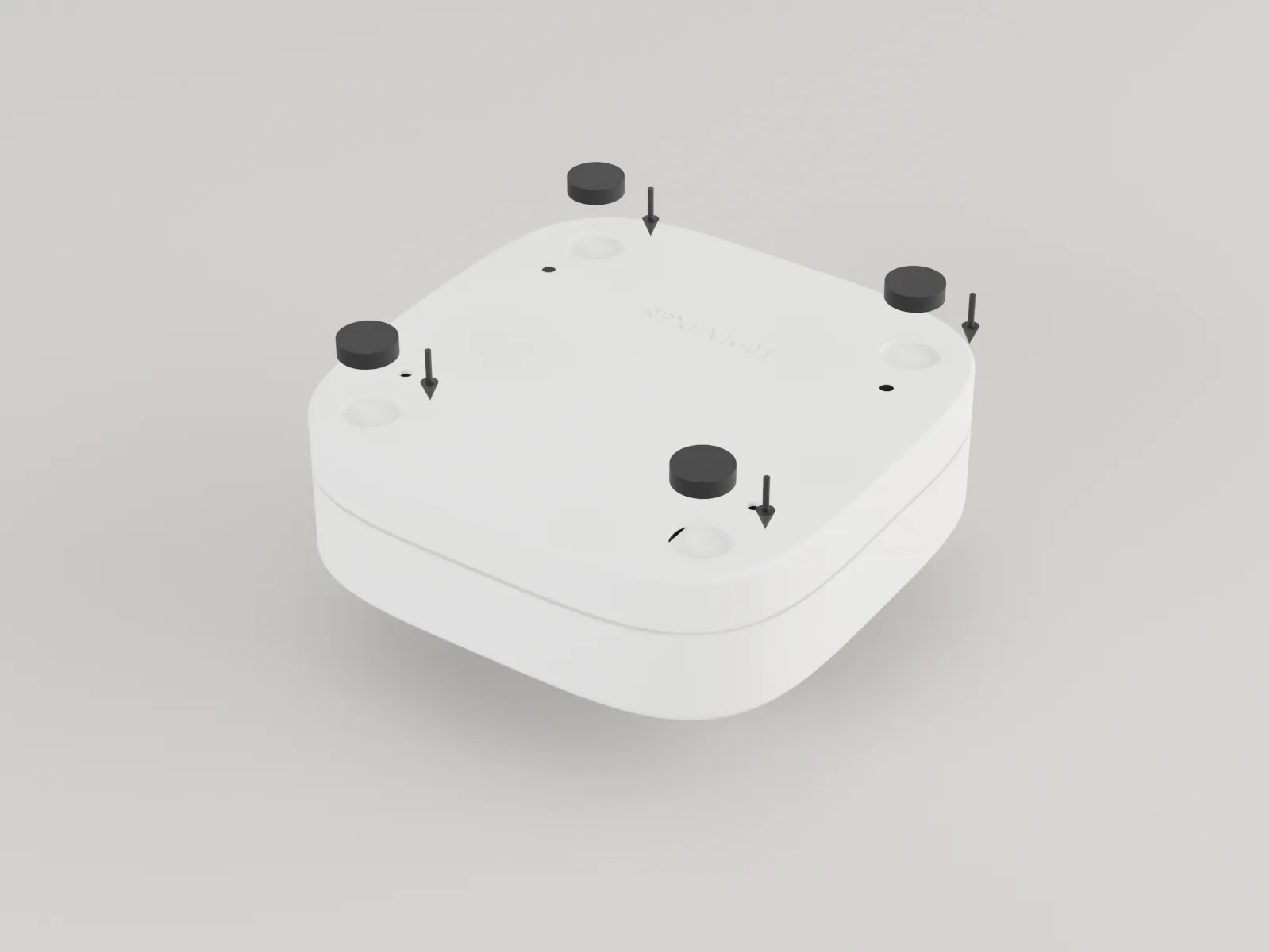
Turn the unit over onto a soft cloth. Press a bumper into each of the four recesses under the corners.
It sits on all four feet without rocking.
Which screw goes where
Only the four face screws are visible. Every other thread is tapped into resin, so drive each screw until it is snug and stop there.
| Where | Screw | Qty | Into | Step |
|---|---|---|---|---|
| Face corners | M3 x 20, black | 4 | through the panel, the deck and the upper body columns into the captive nuts | 12 |
| Captive nuts | M3 hex nut | 4 | the hex pockets in the lower body's corner bosses | 01 |
| Tray to floor | M3 x 4 | 4 | tapped holes through the floor | 02 |
| Leonardo | M3 x 4 | 2 | tapped tray posts at the far end; the two holes by the jack and the digital header sit on printed pins and take no screw | 03 |
| Driver perfboard | M3 x 6 | 1 | tapped boss under the deck | 08 |
| Knob | grub, with the knob | 1 | onto the encoder shaft's D flat | 13 |
| Printed knob | M3 x 6 grub + M3 nut | 1 | nut in the knob's trap, grub in from the side onto the D flat | 13 |
| Light test only | ||||
| Panel to deck | M3 x 10 + nut | 4 | through the corner holes of the panel and the deck into nuts under the deck plate (2, into nut traps, for the optional sector test) | 05 |
| Where | Screw | Qty | Into | Step |
|---|---|---|---|---|
| Face corners | M3 x 20, black | 4 | through the panel, the deck and the upper body columns into the captive nuts | 13 |
| Captive nuts | M3 hex nut | 4 | the hex pockets in the lower body's corner bosses | 01 |
| Battery strap | M3 x 6 | 2 | the two front tapped floor holes | 02 |
| XIAO tray to floor | M3 x 4 | 2 | the two back tapped floor holes | 03 |
| Driver perfboard | M3 x 6 | 1 | tapped boss under the deck | 09 |
| Knob | grub, with the knob | 1 | onto the encoder shaft's D flat | 14 |
| Printed knob | M3 x 6 grub + M3 nut | 1 | nut in the knob's trap, grub in from the side onto the D flat | 14 |
| Light test only | ||||
| Panel to deck | M3 x 10 + nut | 4 | through the corner holes of the panel and the deck into nuts under the deck plate (2, into nut traps, for the optional sector test) | 05 |
First power-up
USB edition: Plug the cable into the back and into your computer. The halo breathes once, then settles to a dim glow. That is all the setup there is: it is a keyboard with two keys.Bluetooth edition: Plug a USB-C cable into the back and into a charger or your computer to charge the cell, then pair it from your computer's Bluetooth settings: it is called RPXL VK-01 BT. The halo breathes once, then settles to a dim glow. That is all the setup there is: it is a Bluetooth keyboard with two keys.
Try it
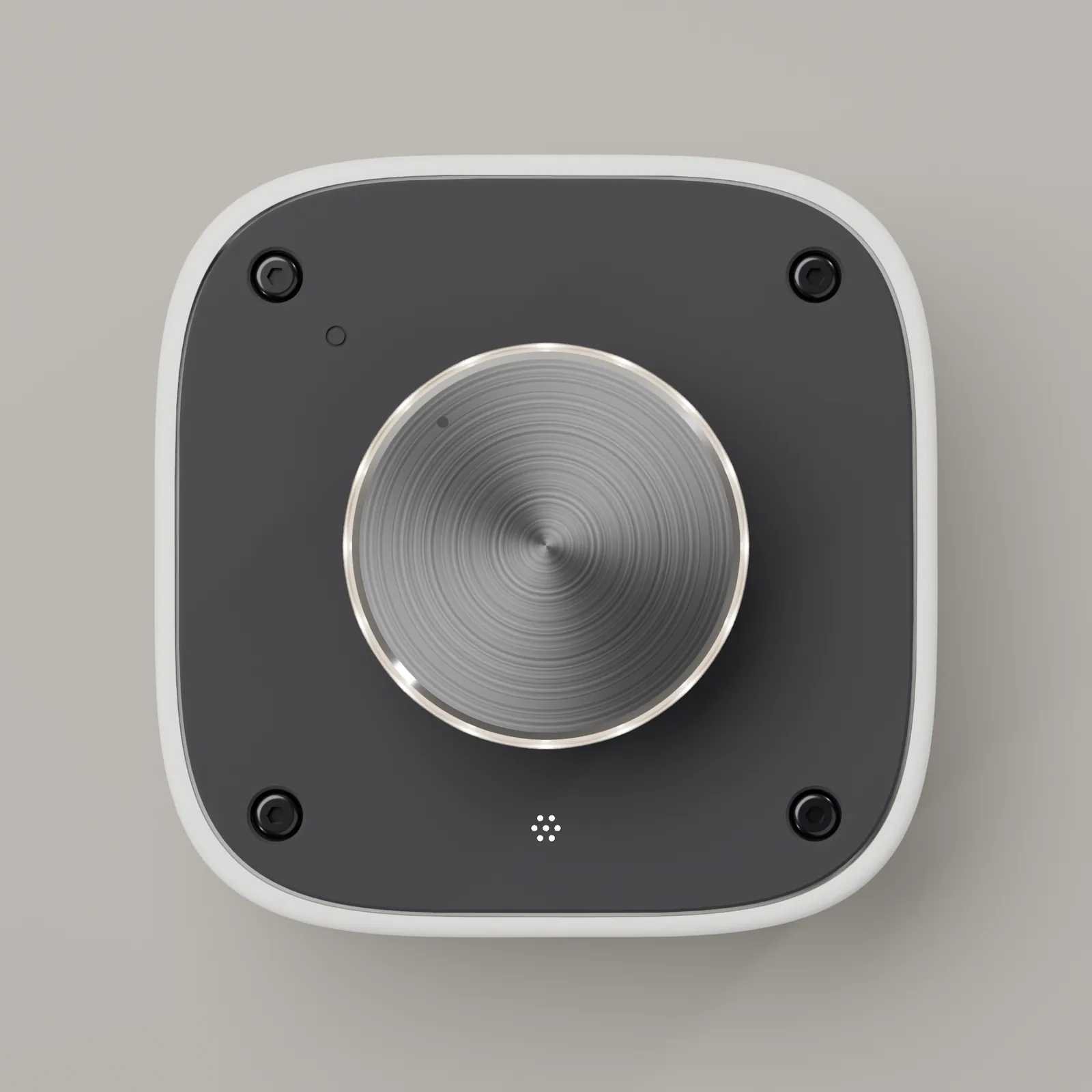
Drag the knob round, or use the buttons. The timings are the firmware's defaults from config.h.
What it does
behaviour| You | The computer | The light |
|---|---|---|
| USB edition: Plug in | sees a new keyboard | one slow halo breath, then a dim idle glow |
| Bluetooth edition: Power up and pair | sees a new Bluetooth keyboard, RPXL VK-01 BT | one slow halo breath, then a dim idle glow |
| Turn one click | volume up or down one step, with its own on-screen volume display | the halo brightens quickly, holds about 1.5 s after the last click, then fades back over about 1 s |
| Press | mute, or unmute | the mute dot lights while muted, and clears on the next press |
| Bluetooth edition: Run on the cell | nothing changes | the halo is dimmer (60 %) and switches off when the cell is low; USB-C power gives it full brightness and charges the cell |
| Bluetooth edition: Leave it alone on the cell | after 10 minutes the knob sleeps | halo and dot off; the next turn or press wakes it, and that first turn is not sent |
| Mute from the keyboard | mutes | no change: the dot follows the knob's own presses only, because it cannot read the computer's mute state |
Every level and timing is a named setting at the top of config.h: HALO_IDLE_LEVEL (0 turns the idle glow off), HALO_HOLD_MS, HALO_FALL_MS, DOT_LEVEL and STARTUP_BREATH_MS.
Troubleshooting
| Symptom | Likely cause | Fix |
|---|---|---|
| Printing and fit | ||
| One side of a part thinner, or a corner peels | plate not level | level again with plain paper (section 04) before changing exposure |
| Dot holes printed closed | over-exposure, or resin left in them | clear with the 0.6 mm bit by hand; recheck the exposure test |
| Groove uneven, or a gap between the halves | a wire or the port plate caught; a rough joint face | open it, reroute, sand the joint face flat on glass |
| Face screw spins without biting | the nut is not seated, or turned in its pocket | take the panel off and press the nut flat (step 1) |
| USB edition: USB plug does not reach the socket | your Leonardo's port differs from the model | measure it against section 04, update params.py, reprint the port plate and tray |
| Bluetooth edition: USB-C plug does not reach the socket | your XIAO's USB-C socket differs from the model | measure it against section 04, update params.py, reprint the port plate and tray |
| Bluetooth edition: The cell does not fit its pocket, or the strap will not close | a thicker cell than 6 mm, or too much foam | use a cell no thicker than 6 mm, thin the foam, and check the lead is not trapped under the strap |
| Knob will not seat, or rubs the moat floor | the shaft's D flat is shorter than 12.0 mm, or the grub is not on the flat | file the flat to 12.0; refit the knob with the grub on the flat |
| Printed knob turns on the shaft | the nut is not in its trap, or the grub is not on the D flat | seat the nut flat in the trap; turn the flat to the grub hole and tighten onto it |
| Ring adapter rocks, or the knob touches it | wrong ring size for the knob, or the plug is not fully down | use the ring for the next size up that matches your knob's diameter; press the plug home and glue it |
| Light | ||
| Bright spots in the halo | an LED not fully home, or bare resin in the chamber | push the LED to its flange; paint the chamber and panel underside white |
| Dot glows with the halo, or light leaks at the edges | a light seal not closed | check the panel sits flat on the tongues; do not overtighten the face screws |
| One halo LED dark | LED in backwards, or a broken joint | check polarity: long lead is the anode |
| Transistor hot | wrong pinout, or the base resistor missing | check E, B, C against your part's datasheet and the 1 k on the base |
| Bluetooth edition: The dot is too faint | a 3.3 V pin leaves little headroom for a white LED | use a dot LED with a forward voltage of 3.0 V or less, or give the dot its own transistor from the cell like the halo (150 ohm, 1 k base) |
| Bluetooth edition: The halo stays dark on the cell, but works on USB-C | the cell is low (below 3.5 V), so the firmware switches the halo off | charge the cell over USB-C |
| Behaviour | ||
| One click moves two steps, or two clicks move one | encoder transitions per click | set ENC_TRANSITIONS_PER_DETENT to 4 or 2 |
| Turning clockwise lowers the volume | encoder direction | set ENC_INVERT to 1 |
| Upload cannot find the board | not in the bootloader | double-tap reset, then upload straight away |
| The dot is lit but the computer is not muted | muted or unmuted from the keyboard, or turning up unmuted it | press the knob to bring them back in step; the dot follows its own presses only |
| Bluetooth edition: It will not pair | asleep, or paired to another device | turn the knob to wake it, remove the old pairing, pair again |
Licence and credits
| What | Licence |
|---|---|
| Code: firmware, the parametric model and its scripts, tests | MIT |
| CAD, print files, this manual and its images | Creative Commons BY-NC-SA 4.0 |
| Fonts embedded in this page: Inter, IBM Plex Mono | SIL Open Font License 1.1 |
| USB edition: HID-Project (USB media keys) | its own licence |
| Bluetooth edition: Seeed nRF52 core and its Bluetooth library | their own licences |
© 2026 Rod Leviton, RPXL / Reactive Pixels. The VK-01 page and the rest of the range: B-Side. More from the studio at reactivepixels.com.