PN-84Network thermal printer
A message from a friend, on paper, on your desk. PN-84 is a palm-sized network printer: people on a short list send it a few lines, end-to-end encrypted, and a slip rises from the slot and waits. No screen, no app, no notifications. Wi-Fi carries the messages, and a LoRa radio keeps a link when the internet does not. You print it, wire it and build it by hand.
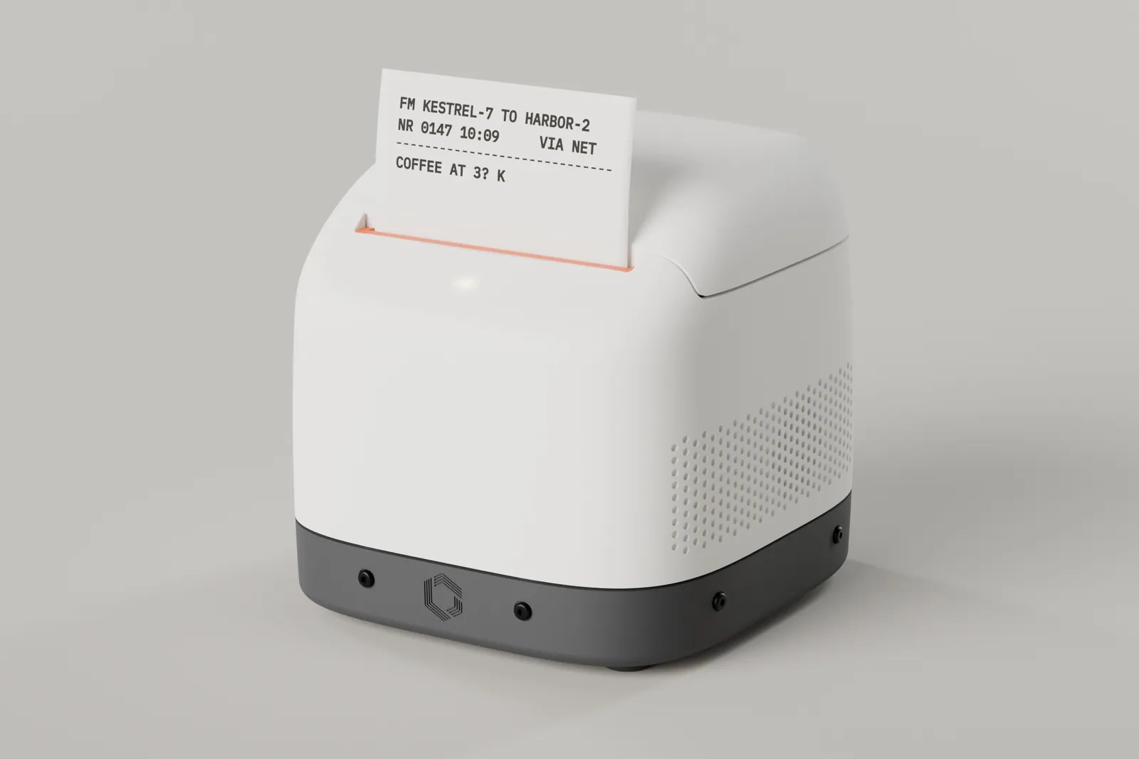
- Core
- 84 x 86mm plate, 59 tall to the printer face
- Paper
- 57 mmrolls up to 40 dia; prints 48 mm, 384 dots
- Power
- USB-C 9 VPD charger, 2 A or more
- Controller
- ESP32-S3XIAO + Wio-SX1262 LoRa
- Messages
- NostrNIP-17, NIP-44 encrypted, contacts only
- Parts
- A$120about, per unit, before tools and paper
This manual is written from the design before the first units are built. Sizes and values of bought parts are nominal until they are measured, and the fit coupons in section 04 decide the final clearances. Follow the bring-up order in section 08 exactly: it is how nominal values become measured ones.
Which chassis are you building?
One product, two ways to print the chassis. Everything else is the same: the printer adapter, the bench base, the electronics, the firmware and the assembly order. Choose yours: the rest of this page then shows that chassis only.
The choice is saved in this browser and written into the address (?edition=resin or ?edition=pla), so a link opens the right manual. It is the only thing this page remembers.
What you're building
Every PN-84 is a core and a shell. The core does all the work and stands on its own; the shell is what you see. They meet at a small documented interface, so anyone can design a shell for the same core. This manual builds both: the core first, then the Pigeon base shell round it.
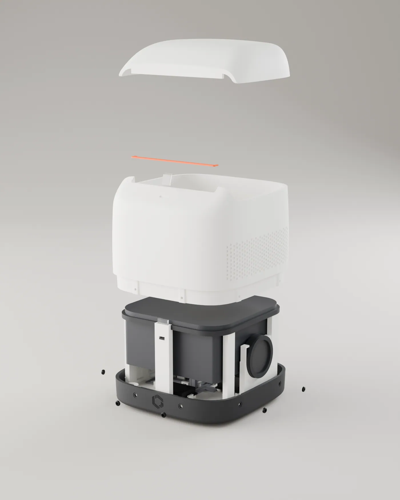
Layer 1: the core
platformThe printer, controller, power, audio and light on one printed chassis, plus the firmware and the message protocol. Engineering first and neutral: no names, jokes or styling. Open hardware and open source.
- Works on the bench with no shell (sections 04 to 09).
- Four M2 screws from below hold it to any shell floor or to the bench base.
- USB-C power on the back, paper exit on top, status light at the front.
Layer 2: the shell
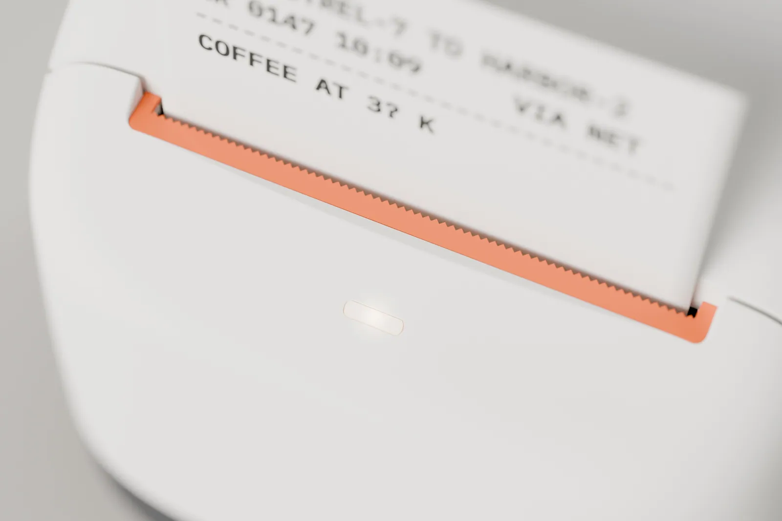
casingThe exterior, the colourways, the slip wording and the sound. The Pigeon base shell (FIG. 0 and FIG. 1) is three printed parts, a band, a deck and a lid, with an orange tear trim, a clear light lens, ten screws, eight magnets and four bumpers. It is built in section 11. Community shells fit the same core through the interface listed there.
- Owns its own floor, feet, lid and outline. The base shell's band is the floor; the lid lifts off for paper.
- Never changes the core; the core never changes for a shell.
- The firmware's wording comes from a voice file, so a shell can bring its own words.
Tools and supplies
Tools
needed- Soldering iron, solder, flux. Every board joint is soldered. A fine tip helps on the XIAO pads.
- Multimeter with a mA range.
- Bench power supply, 0 to 12 V with a current limit (3 A). Every board is first powered on it.
- In-line USB-C power meter that shows volts and amps.
- Calipers, to measure the bought parts and check the coupons.
- Wire strippers, flush cutters, tweezers, a heat gun or lighter for heat shrink.
- Hex driver for M2 button head screws (1.3 mm).
- A 3D printer: resin (MSLA, bed 196 x 122 or larger) with wash and cure, or FDM (0.4 mm nozzle).
- PLA chassis: A soldering iron tip for pressing M2 heat-set inserts.Resin chassis: Sandpaper 400 to 2000 for the light pipe ends and the adapter bezel face.
Supplies and helpful extras
nice to have- USB-C PD charger that offers 9 V at 2 A or more (18 W). A 30 W charger (9 V 3 A) is recommended. Plus a USB-C cable.
- USB-C data cable for the first firmware flash.
- Silicone wire 24, 26 and 28 AWG in the 10 colour set, 1.5 and 3 mm heat shrink, small cable ties (2.5 mm) or waxed lacing.
- Kapton tape over the u.FL antenna connectors.
- Hot melt or UV resin for the XIAO pad joints after the bench test, and a dot of glue for the buck trimmer.
- Oscilloscope and a 0.1 ohm 1 W shunt: strongly wanted for the current tests in bring-up steps 7 and 8.
- A 10 ohm 10 W resistor, optional: a load for checking the PD trigger.
- An SDR or a second LoRa node, optional: proves the radio in bring-up step 11.
Parts to buy
Prices are per unit as listed by Australian retailers or AliExpress in November 2026, GST inclusive where the retailer shows it, shipping not included. Lines marked "est." had no listing and are planning figures. Small parts come in packs, so the cash for a first unit is higher than the per-unit total: allow about A$135 for everything except printing material.
| Part | Spec | Qty | Typical source | A$ each |
|---|---|---|---|---|
| Core: the three main parts | ||||
| Thermal printer | 58 mm embedded panel printer, QR203 / EML203 family, TTL + USB, 5 to 9 V. Usually comes with paper rolls | 1 | AliExpress | about 73 for the three |
| Controller kit | Seeed XIAO ESP32S3 + Wio-SX1262 kit, with its LoRa FPC antenna and Wi-Fi FPC antenna (u.FL) | 1 | AliExpress, Seeed | in the 73 |
| PD trigger | USB-C PD trigger board, fixed 9 V | 1 | AliExpress | in the 73 |
| Core: power, audio, light | ||||
| Buck converter | 9 V to 5 V, set to 5.2 V; at least 1.5 A continuous, input rated 12 V or more (MP1584 class module) | 1 | AliExpress, Core Electronics | 4.00 est. |
| Audio amplifier | MAX98357A I2S class D, 3 W (DFRobot DFR0954 or Adafruit board) | 1 | Core Electronics | 10.15 |
| Speaker | 28 mm dia x about 5 mm, 8 ohm, 1 W class | 1 | DigiKey AU | 6.60 |
| Status LED | 0805 LED, warm white or amber, on a 4 x 3 mm PCB or breakout | 1 | AliExpress, DigiKey AU | 2.00 est. |
| Foam seal ring | closed cell foam, 28 outside, 22.4 inside, about 1.4 to 1.8 thick (cut from foam tape) | 1 | AliExpress, Bunnings | 0.50 est. |
| Core: protection and connectors | ||||
| C1 bulk capacitor | 470 uF 16 V low-ESR electrolytic, 8 x 11.5 (Panasonic FR class) | 1 | DigiKey AU | 0.60 est. |
| C2 ceramic | 10 uF 25 V X5R, 1206 or radial | 1 | DigiKey AU | 0.30 est. |
| F1 resettable fuse | radial PTC, hold 1.6 A, trip 3.2 A, 30 V or more (Littelfuse RXEF160 class) | 1 | DigiKey AU | 1.10 est. |
| D2 TVS diode | SMBJ10A, unidirectional | 1 | DigiKey AU | 0.50 est. |
| D1 Schottky | SS14 (1 A, 40 V), buck to the XIAO 5V pad | 1 | DigiKey AU, AliExpress | 0.20 est. |
| Resistors | R1 1 kohm (LED); R2 10 kohm (only if bring-up step 6 needs it); 1 k + 2 k (optional divider) | 1 set | DigiKey AU | 0.15 est. |
| J1, J2 connectors | JST-XH 2.54 mm pigtail pairs: one 2 pin (J1, power), one 3 pin (J2, data) | 2 pairs | AliExpress | 0.40 est. |
| Wire and sundries | silicone wire, heat shrink, labels, ties, solder (share of the packs) | 1 set | AliExpress, Core Electronics | 3.00 est. |
| Fixings | ||||
| Resin chassis: M2 hex nut | AF 4.0, 1.6 thick, captive in the chassis bosses | 4 + 2 | AliExpress, Bunnings | 0.05 est. |
| PLA chassis: M2 heat-set insert | for a 3.2 mm hole, 4 deep | 4 + 2 | AliExpress | 0.10 est. |
| M2 x 10 screw | ISO 7380 button head, black; core to the bench base or a shell floor | 4 | AliExpress, Bunnings | 0.15 est. |
| Rubber feet | 10 dia x 3, self-adhesive; optional, for grip under the bench base (the base shell uses the bumpers below) | 4 | AliExpress, Bunnings | 0.30 est. |
| Base shell (section 11) | ||||
| M2 x 8 screw | ISO 7380 button head, black; core up through the band floor into the corner bosses (the bench base takes M2 x 10) | 4 | AliExpress, Bunnings | NOMINAL |
| M2 x 6 screw | button head (ISO 7380 head shape), thread-forming, black; band into the deck skirt bosses | 6 | AliExpress | NOMINAL |
| Bumper | round self-adhesive bumper, 10 dia x 3.5; one in each band recess, over a core screw | 4 | AliExpress, Bunnings | NOMINAL |
| Disc magnet | N35, 5 x 2 mm; four pressed into the lid bosses from above, four into the deck rim bosses from below, press fit plus a drop of CA glue | 8 | AliExpress | NOMINAL |
| Tear trim | printed, orange: the toothed U trim round the paper slot (section 04) | 1 | you print it | in material |
| Light lens | printed, clear resin: the 6.3 x 1.0 pipe through the deck over the light port (section 04) | 1 | you print it | in material |
| Shell material | PLA or tough resin in your colourway for the deck and lid, the band colour for the band, orange for the trim; about 95 cm3 solid for the three main parts | about 0.13 kg | any | NOMINAL |
| Printing material | ||||
| Resin chassis: Resin | tough or ABS-like opaque resin for the chassis, adapter and bench base; clear resin for the light pipe | about 0.24 kg | AU resin suppliers | about 12 |
| PLA chassis: PLA or PETG | any colour; plus a clear resin light pipe (or ask a friend with a resin printer) | about 0.2 kg | any | about 5 |
About A$120 per unit for the core parts, fixings and printing material at the prices above. The base shell's screws, bumpers and material are NOMINAL and not in this total.
The USB-C PD charger and cable, a USB-C data cable, tools, and spare paper. Paper is generic 57 mm thermal roll, 40 mm diameter or less (57 x 38 rolls fit), BPA free.
Print the parts
Print the fit coupons before anything else. They print three sizes of every tight fit; the size that fits your parts and your printer is the one you set before printing the chassis.
What gets printed
every file as .stl and .3mf| Part | Part file | Build plate | Qty |
|---|---|---|---|
| Resin chassis: Chassis (captive nuts) | pn84_core_chassis_resin | pn84_plate_resin_2_chassis_adapter | 1 |
| PLA chassis: Chassis (heat-set inserts) | pn84_core_chassis_pla | pn84_plate_pla_2_chassis_adapter | 1 |
| Printer adapter | pn84_printer_adapter | pn84_plate_resin_2_chassis_adapterpn84_plate_pla_2_chassis_adapter | 1 |
| Bench base | pn84_bench_base | pn84_plate_resin_3_bench_basepn84_plate_pla_3_bench_base | 1 |
| Light pipe (clear resin) | pn84_light_pipe | pn84_plate_clear_light_pipe | 3, keep the best |
| Shell band (band colour) | PN84_p5_band | single part | 1 |
| Shell deck (body colour) | PN84_p5_deck | single part | 1 |
| Shell lid (body colour) | PN84_p5_lid | single part | 1 |
| Magnet pull-test coupon | PN84_magnet_coupon (in out_H3) | single part | 1, on arrival day |
| Tear trim (orange) | PN84_p5_trim | single part | 1, or 2 to keep the best |
| Light lens (clear resin) | PN84_p5_lens | with the light pipes | 2, keep the best |
| Fit coupons | pn84_coupon_* | pn84_plate_resin_1_couponspn84_plate_pla_1_coupons | 1 each |
Build plates come with the print rotations already applied (3MF, one object per part, so each part can still be moved). The STL of a plate is one fused mesh for a quick look. Plates are laid out for a 196 x 122 bed and use 186 x 112 of it; any FDM bed that size or larger takes the PLA plates.
Print order
five prints, then the shell- Coupons. About an hour of resin or two of PLA. Test each with the real part. Each coupon carries three sizes marked with 1, 2 and 3 notches.
- Chassis, in the variant you chose: Resin chassis: resin with captive nut wells.PLA chassis: PLA with heat-set insert holes.
- Printer adapter. The ring the printer clips into. It is the one part to reprint if your printer differs from the QR203 family, so print it after the chassis (or with it, if the coupons already agree).
- Bench base. Stands the core on a desk with no shell. PLA is the easiest material for it.
- Light pipe, clear resin, any time. Print three and keep the best polished one. Print the shell's light lens on the same plate.
- The shell, once the core has passed bring-up: band, deck, lid and the tear trim. The shell files are single parts in the CAD frame (
cad/plasticity/p5/out_H3/: deck, lid and band, with the magnet bosses), so rotate them in the slicer as the table below says.
The coupons
what each one proves| Coupon | Fits when | Sizes | Setting |
|---|---|---|---|
| coupon_clip_land | the printer's side clip latches under the land with no play | land thickness 1.5, 2.0, 2.5 | PANEL_T |
| coupon_adapter_pin | the adapter ring presses onto the chassis pins (post block and ring strip) | hole 1.6, 1.7, 1.8 | ADAPTER_HOLE_D |
| Resin chassis: coupon_nut_pocket | an M2 nut drops in and does not turn | nominal and 0.1 either side | NUT_POCKET_AF |
| PLA chassis: coupon_heatset | an M2 insert presses in square | nominal and 0.1 either side | HEATSET_D |
| coupon_usb_opening | a USB-C plug seats fully (for shell designers) | nominal and 0.2 either side | USB_RECEPTACLE |
| coupon_speaker_seat | the 28 mm speaker presses past the lips and sits square | one size | SPK_SEAT_CLEAR |
| PN84_magnet_coupon | two blocks with a magnet each, skin to skin, pulled apart on a kitchen scale hold 40 to 75 g per pair. Too strong: raise MAG_SKIN by 0.2 and reprint | one size | MAG_SKIN |
| coupon_light_pipe | the pipe slides in with no rattle and the LED PCB sits in its pocket | 0.10, 0.15, 0.20 per side | PIPE, CLEAR |
Never scale a part to fix a fit. Put the winning sizes into cad/core_params.py, then from cad/ run python -m pytest, python tools/write_interface.py and python -m ticker.printing to rebuild the print files. The tests name any clearance that a change breaks.
Orientation and supports
rotations from the STL frame, degrees, right-hand rulePart files lie in the STL frame: lowest point on z = 0, chassis seat face down, adapter bezel face up, bench feet down. If your slicer's sign is the other way, use the check column.
| Part | Rotate | Check after rotating | Keep supports off |
|---|---|---|---|
| Chassis | X -30 | the front end (the little light column) is the high edge | post tops and pins, nut wells, board lips, fences and tab barbs, PD rail slots, antenna clips, pipe slot and LED pocket. Supports go on the seat face (sand flat) and a few inside the speaker bore |
| Printer adapter | X 195 | bezel face down, clip pockets open upward, front edge (column notch) high | clip pocket roofs, the opening walls, the pin holes, the column notch. Sand the bezel face flat on 1000 grit |
| Bench base | X -15 | feet down on the supports, top face up, the end without the USB cut-out high | the top face (core seat) and the four screw holes. 3 to 4 raft layers; if it cups, print it in PLA |
| Light pipe | none | lying on its 7.8 x 11 back face | both end faces. No supports |
| Shell deck | tilt about 30 | open skirt toward the build plate, front (slot side) high | the whole outside: slot, trim pocket, light hole, grille. Supports go on the skirt edge and the inside of the roof only. It is open, so it needs no drain holes |
| Shell lid | tilt about 30 | open rim toward the build plate, front edge high | the outside and the front edge (it closes against the paper slot). Supports on the rim and the inside only |
| Shell band | tilt about 20 | floor toward the build plate, the USB-C pill high | the outer wall (mark, screw spot faces, USB-C pill) and the top edge. Supports on the floor underside; the bumpers cover the four recesses |
| Tear trim | none | flat, the visible face away from the plate | the toothed edge. Print it flat on light supports or straight on the plate |
| Light lens | none | clear resin, lying on its side as the light pipe | both end faces. Sand the outer face flush with the deck afterwards if it stands proud |
| Coupons | clip land X 180, others none | clip land: pocket roofs up, notched end up | the faces each coupon tests |
| Part | Rotate | Check after rotating | Supports |
|---|---|---|---|
| Chassis | none | seat face on the bed, posts and frame pins up | only a few inside the speaker bore (a 28 mm arch); light scars there are fine, it is the glue land |
| Printer adapter | X 180 | bezel face on the bed, pockets open upward | none; keep supports out of the 1.7 pin holes |
| Bench base | X 180 | top face on the bed, feet up | none; add a 5 mm brim |
| Light pipe | resin only | clear resin, lying on its back face | none |
| Shell deck | none | upright as it sits, skirt on the bed | inside only, under the roof and the paper bay floor; the outside needs none. Tree supports, 0.16 layers, 3 perimeters |
| Shell lid | none | upright as it sits, rim on the bed | inside only, under the roof |
| Shell band | none | upright as it sits, floor on the bed | none; the counterbores bridge. 0.12 layers if you want the mark sharper |
| Tear trim | none | flat, visible face up | none. 0.1 layers; the 0.45 teeth come out rounded on a 0.4 nozzle, so resin is better for this one part |
| Light lens | resin only | clear resin, as the light pipe | none |
| Coupons | clip land X 180, others none | clip land: pocket roofs up | speaker seat: light supports on the foot side only |
Layer 0.05 mm, normal exposure for your resin. Use a tough or ABS-like resin for the chassis and adapter: the 0.8 mm flex tabs and the clips must bend and come back, and a brittle standard resin snaps. Do not hollow any part. Holes print 0.05 to 0.1 small, which is what the coupons decide. Wash and cure lightly (over-curing makes the tabs brittle) and remove supports before the final cure.
0.4 mm nozzle, layer 0.16 mm (0.2 acceptable), 4 perimeters (1.6 mm walls), 5 top and 5 bottom layers, 30 percent gyroid. Turn on thin wall detection so the 0.8 flex tabs and 1.0 clip arms print as single walls. Elephant foot compensation 0.1 mm if available. PETG is tougher for the snap features. Heat-set holes (3.2 dia x 4 deep) open from the plate underside.
Clear resin, support-free on its back face. Wash, then sand both end faces from 400 up to 2000 and clear-coat or dip them. The pipe is 7.8 x 11 x 1.6 and delicate, which is why there are three on the plate.
The hexagon mark on the band front is debossed 0.3 deep in 12 stripes about 0.28 wide with 0.22 gaps. They come out crisp in resin. On a 0.4 mm nozzle the stripes soften and run together into a plain hexagon; that is expected, and the mark still reads.
Bench base
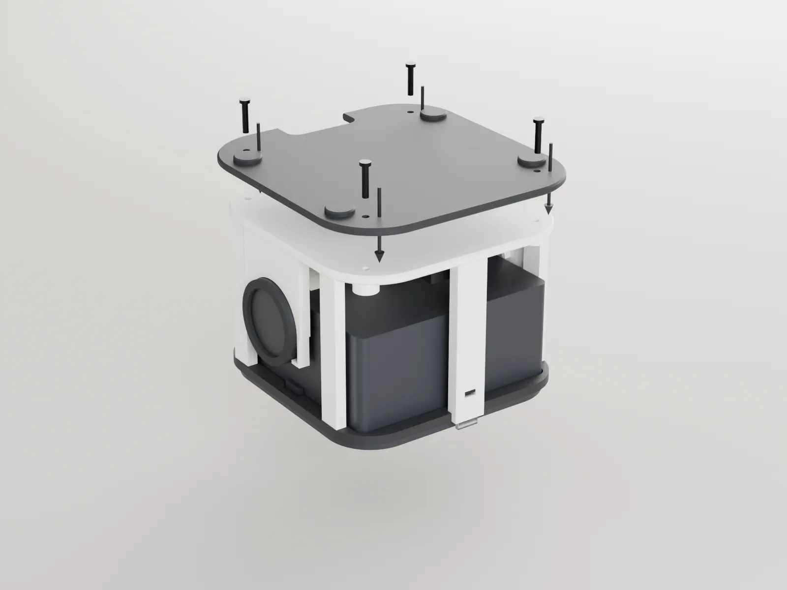
The bench base stands in for a shell floor, so the core can live on a desk while you test it, use it, or wait for a shell. It puts the core's seat at exactly the height a shell would, so the same four screws and the same seat plane apply.
- A flat plate 88 x 92 x 2.5 with four printed feet 1.5 tall. The screw heads sit in the foot height, clear of the desk.
- Four 2.3 mm holes on the core's boss axes (32, 33.5 from the centre).
- A cut-out at the back for the USB-C plug and its cable, wide enough that the PD board can still be pushed out backwards for service.
Print it in PLA top face down with a brim; it is the easiest of the parts. It goes on last, in step 15, once the core has passed bring-up.
Wiring and harness
USB-C power comes in at the back at 9 V, through a fuse to a single star point. The printer takes 9 V from the star; everything else runs from a 5.2 V buck. Grounds form a tree from the star: no loops.
The printer is never powered from the XIAO 5V pin. And check the PD trigger's output on its own before connecting anything to it: above 9.45 V, stop (the printer is rated 9 V maximum). Bring-up step 2 does this.
Conventions
colour, gauge, ends| Colour | Carries | Gauge |
|---|---|---|
| Red | +9 V | 24 AWG printer and PD leads, 26 AWG to the buck |
| Orange | +5.2 V | 26 AWG |
| Black | ground; every pair carries its own | as its pair |
| Yellow | printer data, XIAO to printer RX | 28 AWG |
| Blue / purple / grey | I2S bit clock / word select / data | 28 AWG |
| Brown / white | speaker + / speaker - (not ground) | 26 AWG |
| Green | LED anode | 28 AWG |
Cut length is the routed length plus 10 mm per end, plus 20 mm where there is a service loop. Each joint gets 1.5 mm heat shrink, and each wire a heat-shrink label with its W number at the board end. J1 (2 pin, power) and J2 (3 pin, data) are the only connectors, both at the printer so it lifts out; their pin counts differ, so they cannot be swapped.
Wire list
lengths nominal| W | From | To | Signal | AWG | Cut mm |
|---|---|---|---|---|---|
| 9 V | |||||
| W1 | PD trigger VOUT+ | star (C1 +), through F1 inline | +9 V | 24 | 45 |
| W2 | PD trigger GND | star (C1 -) | GND | 24 | 45 |
| W3 | star | J1 pin 1, printer power | +9 V | 24 | 95 |
| W4 | star | J1 pin 2 | GND | 24 | 95 |
| W5 | star | buck IN+ | +9 V | 26 | 75 |
| W6 | star | buck IN- | GND | 26 | 75 |
| 5.2 V | |||||
| W7 | buck OUT+ | XIAO 5V pad, D1 inline at the buck | +5.2 V | 26 | 75 |
| W8 | buck OUT- | XIAO GND pad | GND | 26 | 75 |
| W9 | buck OUT+ | amp VIN | +5.2 V | 26 | 50 |
| W10 | buck OUT- | amp GND | GND | 26 | 50 |
| Signals | |||||
| W11 | XIAO D4 | J2 pin 1, printer RX | data, 3.3 V | 28 | 105 |
| W12 | XIAO GND | J2 pin 3, printer TTL GND | spare, only if bring-up step 6 needs it | 28 | 115 |
| W13 | XIAO D1 | amp BCLK | I2S bit clock | 28 | 90 |
| W14 | XIAO D2 | amp LRC | I2S word select | 28 | 90 |
| W15 | XIAO D3 | amp DIN | I2S data | 28 | 90 |
| W16 | amp OUT+ | speaker + tab | speaker | 26 | 40 |
| W17 | amp OUT- | speaker - tab | speaker (not ground) | 26 | 40 |
| W18 | XIAO D0 | LED PCB anode (R1 on the PCB or inline) | LED | 28 | 160 |
| W19 | XIAO GND | LED PCB cathode | LED return | 28 | 175 |
| W20 | printer TX | J2 pin 2, XIAO D5 (divider if 5 V) | status; not fitted | 28 | 105 |
Inline parts: F1 in W1 about 10 mm from the PD pad; D1 in W7 at the buck, band (cathode) toward the XIAO; D2 and C2 soldered across the C1 leads, which are the star. The two antenna leads are the kit's own u.FL pigtails: press fully home, cover with Kapton, and never put a tie over the coax.
XIAO pads
top view, USB-C toward the back| Left column (toward the antenna fin) | Right column (toward the centre) |
|---|---|
| D0 LED, W18 | 5V W7 (through D1) |
| D1 BCLK, W13 | GND W8, W19 |
| D2 LRC, W14 | 3V3 R2 (option) |
| D3 DIN, W15 | D10 LoRa MOSI, inside the kit |
| D4 printer data, W11 | D9 LoRa MISO, inside the kit |
| D5 printer TX return, W20 (not fitted) | D8 LoRa SCK, inside the kit |
| D6 free (debug UART TX) | D7 free (debug UART RX) |
D6 and D7 are the ESP32-S3's UART0, which prints the boot log on every reset. On D4 the printer never sees it, and the firmware drives D4 high as its first action. If a stray character still prints after power-up (bring-up step 6), fit R2: 10 kohm from D4 to 3V3.
Firmware
One sketch (firmware/papernet/) with one settings file, config.h. Every pin, baud rate, heat value and layout size lives there. The printed wording comes from a voice file: VOICE_PLAIN is the neutral platform default, VOICE_PAPERNET is the Pigeon shell's wording.
Build
from firmware/arduino-cli core update-index
arduino-cli core install esp32:esp32
arduino-cli compile --fqbn esp32:esp32:XIAO_ESP32S3 --libraries libraries papernet
# the Pigeon voice, without editing config.h:
arduino-cli compile --fqbn esp32:esp32:XIAO_ESP32S3 --libraries libraries \
--build-property "compiler.cpp.extra_flags=-DVOICE_PAPERNET" papernetKeep the board defaults (USB CDC On Boot enabled, 8 MB flash, default 8 MB partitions with two app slots, PSRAM off). --libraries libraries is required: it adds the protocol core, the power and bench library and libsecp256k1 kept in the repository. Everything else ships inside the esp32 core; do not install the separate "QRCode" Arduino library.
First flash
over the XIAO's own USB-C- Connect the XIAO to the computer with a data cable. It may stay plugged in with the 9 V supply on: D1 keeps the two apart.
arduino-cli board listshows it. If not, hold BOOT, press and release RESET, then release BOOT. - Upload.
arduino-cli upload --fqbn esp32:esp32:XIAO_ESP32S3 -p /dev/cu.usbmodemXXXX papernet. Press RESET if it stays in download mode. - Open the console.
arduino-cli monitor -p /dev/cu.usbmodemXXXX. The boot log shows the reset cause,printer on D4/D5 at 9600 baud, heat n1 1 (auto), the device key and the command list. - Optional, updates over the air. Set a password now:
ota pass <8 to 63 characters>. Later,ota onopens a 15 minute window on the home network.
First boot: the setup slip
no app, no accountOn its first boot the printer makes its own identity key and prints a setup slip with a QR code. The QR is a Wi-Fi join code for the printer's own setup network; its password exists only inside the QR.
- Scan the QR with a phone. The phone joins the printer's network and the setup page opens by itself.
- Choose your home Wi-Fi and enter its password.
- Note the printer's public key (npub): senders need it.
- Pick a display id: 3 to 8 letters, a dash, one digit (for example
HARBOR-2). Save; the printer restarts onto your Wi-Fi.
Whoever holds it can open the admin page while it is on (portal over USB opens it for 15 minutes). setup prints it again; portal reset forgets the Wi-Fi and starts setup over; factory erases everything, including the identity key.
selftest test slip, power power budget and brownout count, baudscan and baud N, heat, density, sweep, burst, lora probe, dry on (slips to the terminal instead of paper), help.
Bring-up on the bench
Power each part on its own, on a current-limited supply, before anything is joined. A step that fails stops the run until it is understood. Record every value; each one replaces a nominal figure in the firmware or the CAD.
- Boards one at a time. Buck alone at 9.0 V, 100 mA limit: turn the trimmer to 5.20 V and glue it. Amp alone at 5.2 V. XIAO on USB through the power meter, with both antennas fitted. LED through R1 at 3.3 V.buck 5.15 to 5.25 V; amp idle under 10 mA; XIAO idle under 150 mA
- PD trigger, nothing connected. Charger, cable, trigger; meter on the output pads after 2 s.8.55 to 9.45 V. Above 9.45 V stop: do not connect the printer
- Protection star and harness. Build the star (C1, C2, D2) and W1 to W6. 9.0 V, 200 mA limit into the star; then the reverse check at 100 mA for one second; then continuity of every W.under 5 mA after charging; reversed, the supply limits; no shorts
- Printer at 5 V, alone, 2.0 A limit, paper in. Hold FEED while switching on: the printer's own self-test prints. Note its baud rate and measure its TX idle level.idle under 100 mA; the slip is legible
- Printer at 9 V, bench supply (3 A limit), then on the real chain: charger, trigger, star, J1.self-test complete, the trigger does not cut out, 8.0 V or more during printing
- Controller and printer link. Flash, then
lora probe; wire W11 (D4 to printer RX) and a ground;baudscan,baud N,selftest; reset the XIAO ten times.probe PASS, 0x1424; one rate prints clean; both edge marks print, ruler 48.0 mm; no stray characters - Current burst test. Bench supply, 3 A limit, scope on a 0.1 ohm shunt:
burst 7, thenburst(auto) three times on the PD chain, thenpower.9 V sag 0.5 V or less; no resets; brownout count 0 - Darkness.
sweep, pick the lowest heat time with a solid black bar and separate checkerboard dots; trydensity 10,14,18; setheat.solid black, no bleed; the last line clears the tear edge afterfeed - Wi-Fi and messages.
factory, scan the setup slip, finish setup. Add a contact; send to the printer and back (section 12). A message from a key that is not a contact must not print.send to slip under 30 s; non-contact held as pending - Sound and light.
msg KESTREL-7 HARBOR-2 TEST: the arrival sound plays, then the slip prints. Check the four light patterns through the pipe.clear sound, no rattle; LED visible, not glaring - LoRa.
lora probeon buck power;lora cw 2000 14sends a 2 s carrier at 923 MHz. The radio link itself is still in development; this proves the module and antenna feed.current rises about 45 to 60 mA; carrier seen on an SDR if you have one - Soak, assembled. After section 09: twenty message slips and three self-tests back to back on the PD charger, then
powerand a touch check.all 23 clean, no resets; buck and trigger under 60 C, printer under 50 C
The firmware keeps the print head's peak current inside the charger's 9 V rating (heat auto). Forcing a larger heat block makes the charger cut out and the printer restart mid-slip. Do it only on a current-limited bench supply, as in step 7.
Assembly
Assemble only after the electronics have passed bring-up steps 1 to 11 loose on the bench. Each part goes in along its own direction with the earlier parts already in place; the order matters. Images show the part being fitted lifted off its seat, with an arrow in the direction it goes in.
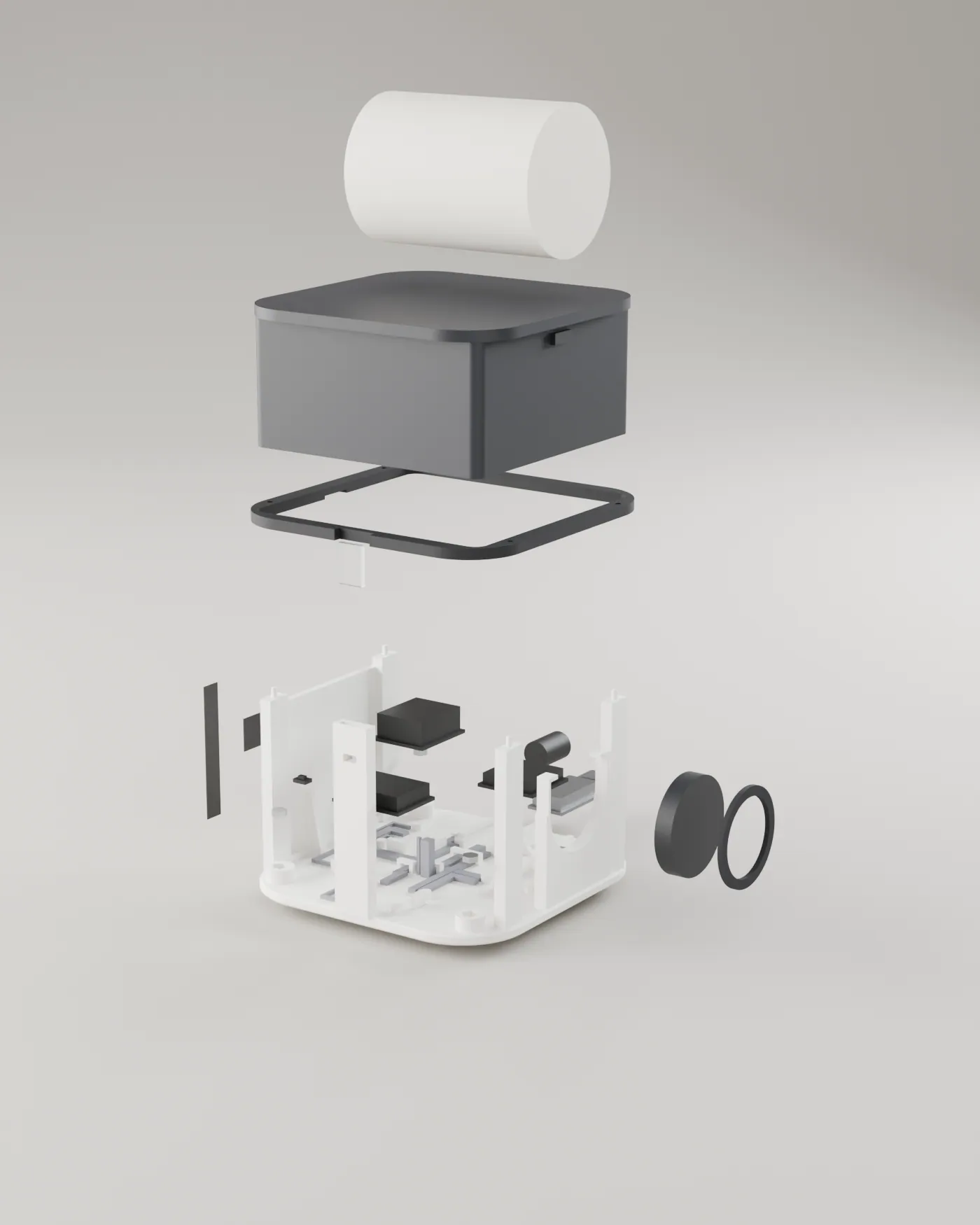
- Chassis
- 01Nuts or inserts
- 02LED
- 03Light pipe
- 04Antennas
- Boards
- 05Buck
- 06Amplifier
- 07XIAO + Wio
- 08PD trigger
- 09Capacitor and star
- 10Speaker and seal
- 11Wiring
- Printer
- 12Printer adapter
- 13Printer
- 14Paper
- Finish
- 15Bench base
- 16Test
-
01
Fit the four fixings
4 x M2 nut4 x M2 heat-set insert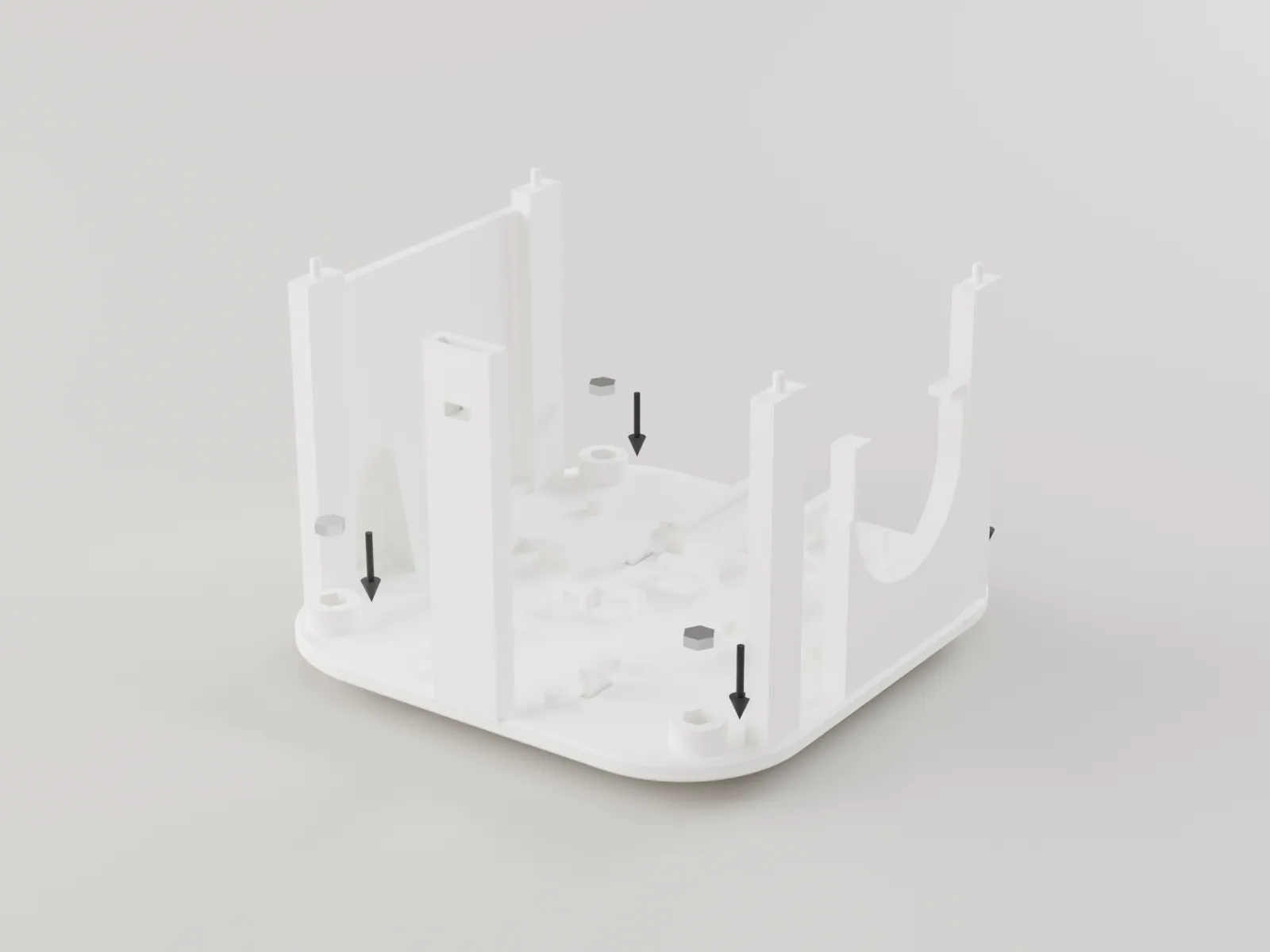
Resin chassis: Drop an M2 nut into the hex well in each corner boss (the wells open upward). A dot of glue keeps each one in when the chassis is turned over.
PLA chassis: Turn the chassis over and press an M2 heat-set insert into each boss hole from the plate underside with the soldering iron, flush with the seat face.
The nuts sit flat and do not turn.
Each insert is square and flush, not proud of the seat face.
-
02
Fit the LED
LED PCB, W18, W19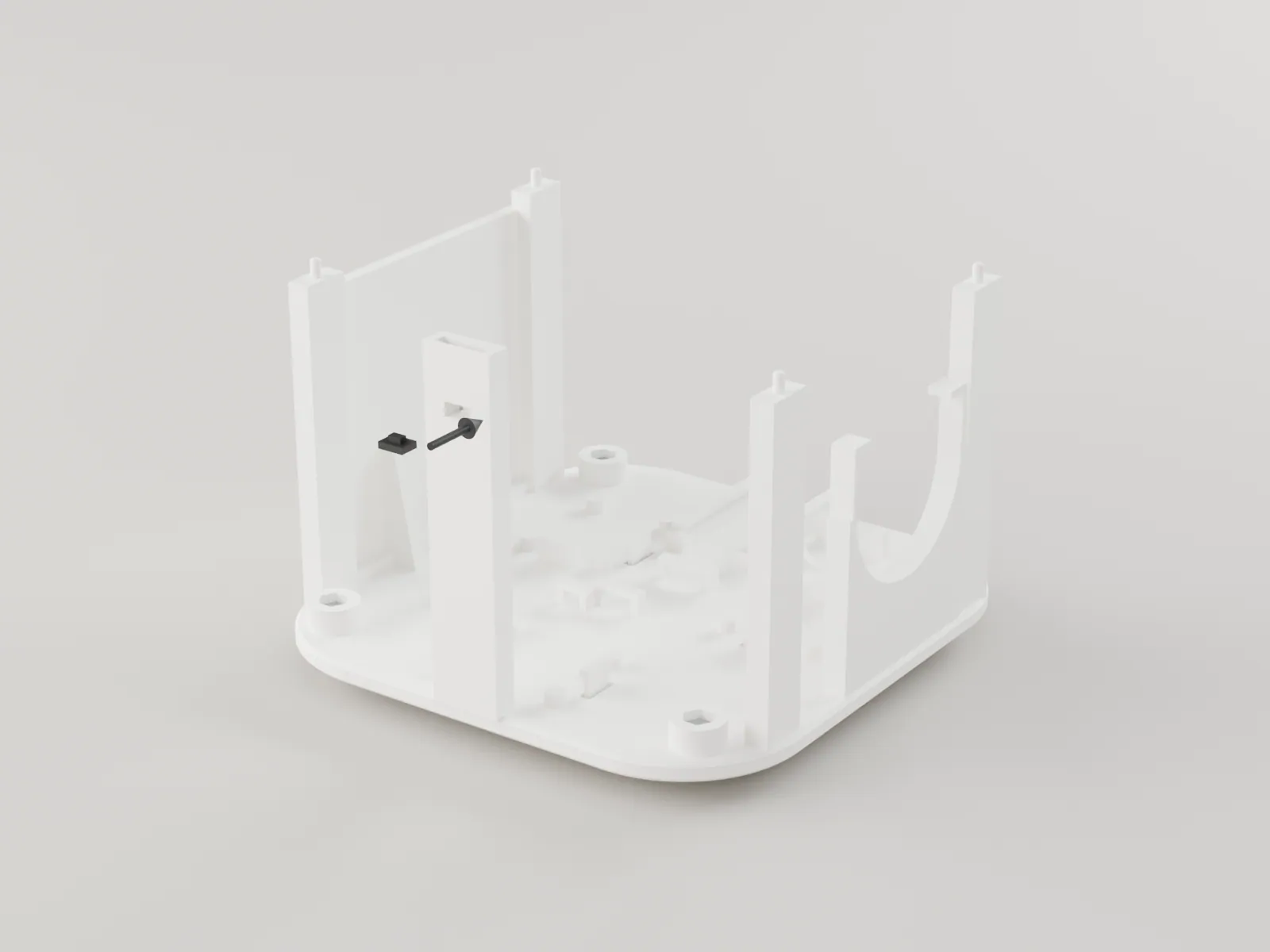
Solder W18 (green, anode) and W19 (black, cathode) to the LED PCB, with R1 on the PCB or inline. Feed the wires down the channel at the back of the light column and slide the PCB into its pocket from the front, LED up.
The LED faces up into the column.
-
03
Drop in the light pipe
clear light pipe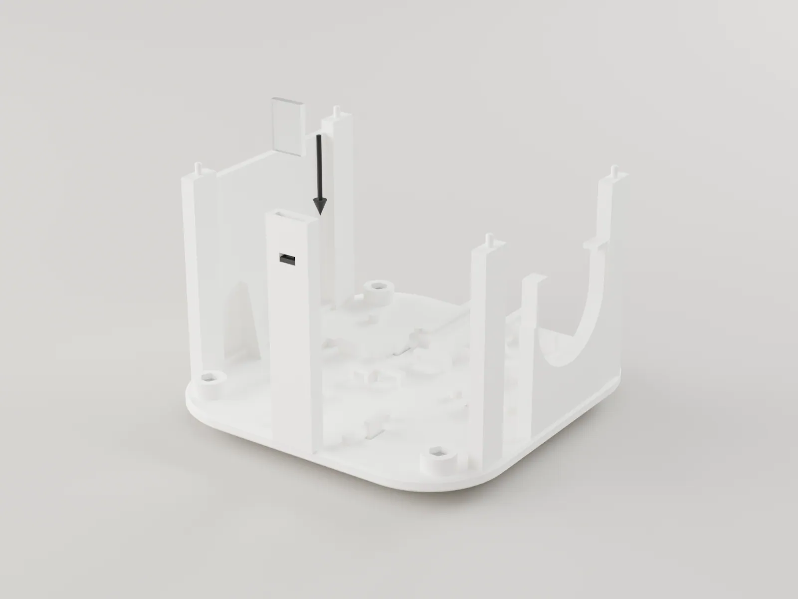
Drop the polished pipe into its slot from above until it rests just over the LED. Its top end is the light port, level with the printer face; a shell's lens sits over it.
The pipe slides in with no rattle and both polished ends are clean.
-
04
Fit the antennas
LoRa FPC, Wi-Fi FPC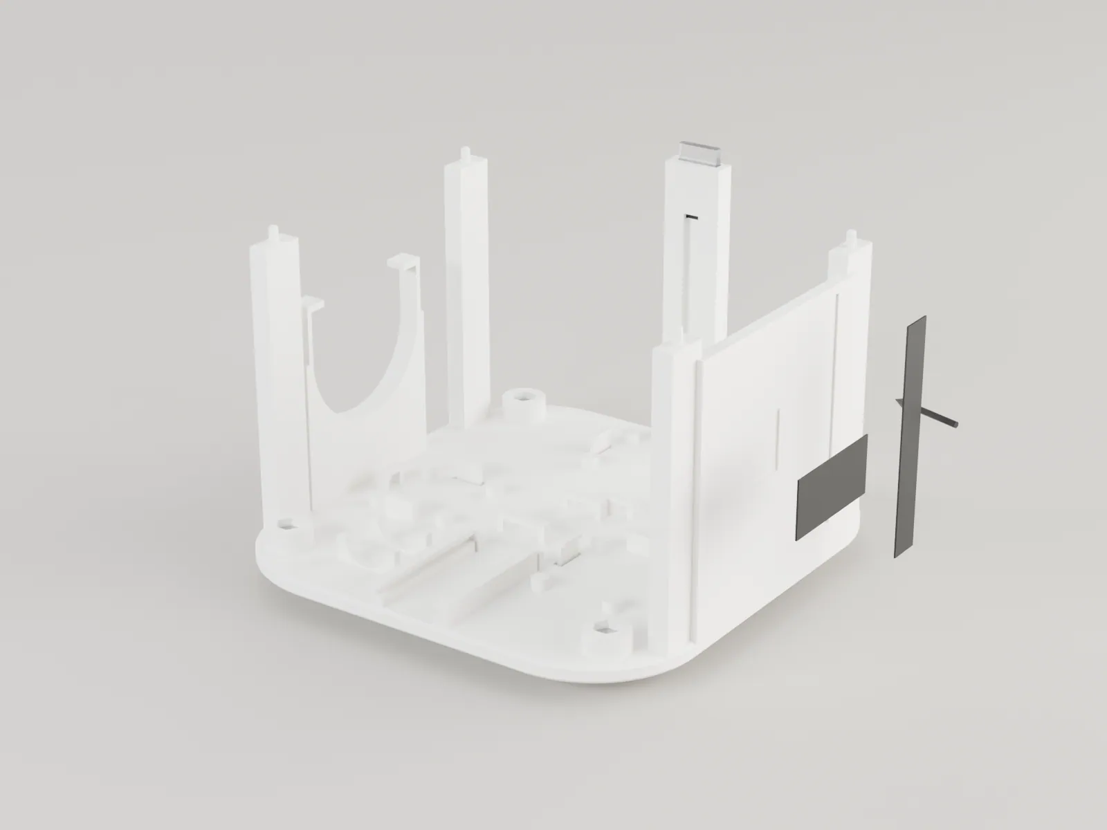
Both antennas are flat FPCs on the outside of the left fin, each in its shallow recess. Stick the LoRa FPC upright on the front half, feed end down; the Wi-Fi FPC on the back half. Plug the leads into the Wio and XIAO u.FL sockets, fully home, Kapton over each. Coil spare coax at 10 mm radius or more, never under a tie.
Antennas are fitted before any firmware that could transmit is run.
-
05
Click in the buck
buck converter, set to 5.2 V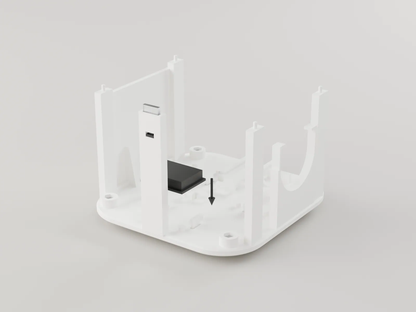
Tuck the board under the lip on its left fence and press it down until the flex tab on the right clicks over the edge. Input pads toward the back.
The trimmer is glued at 5.20 V (bring-up step 1).
-
06
Click in the amplifier
MAX98357A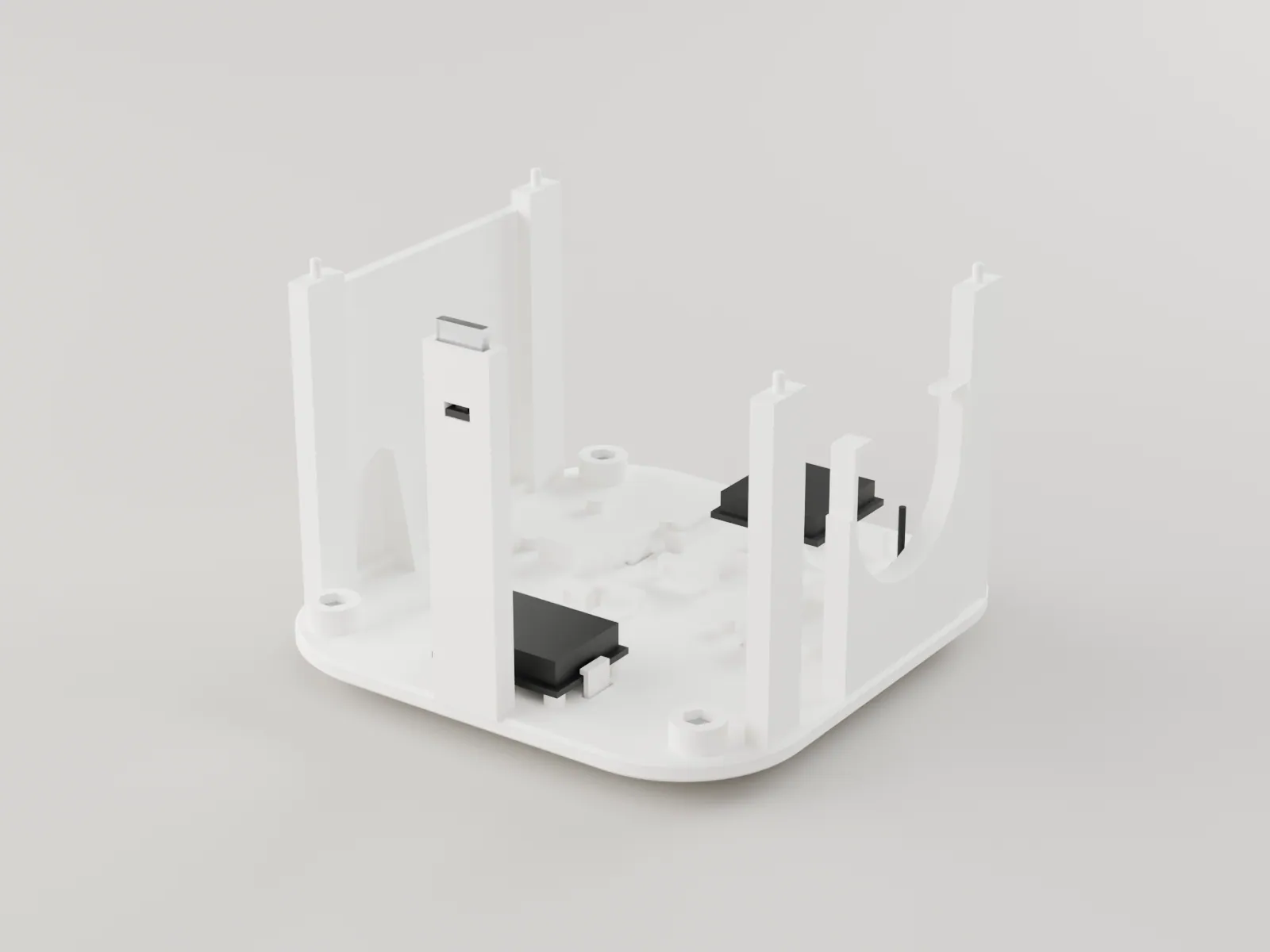
The same way: under the back lip, then click the front tab. Speaker terminals toward the right.
-
07
Click in the XIAO + Wio
controller stack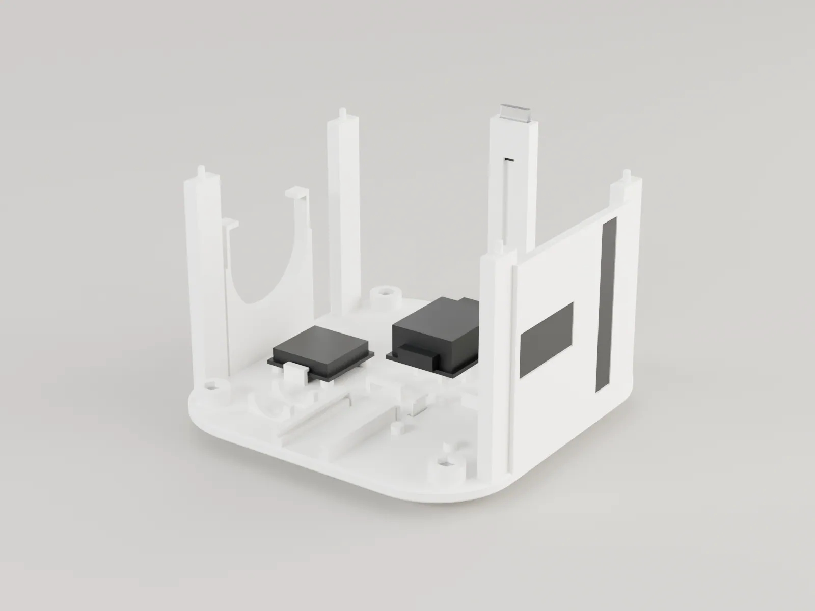
Under the front lip, then click the right tab. Its own USB-C faces the back, with a clear plug path for flashing later.
The flex tab barb lands on a pad you do not solder; move it if it does not.
-
08
Slide in the PD trigger
PD trigger, from the back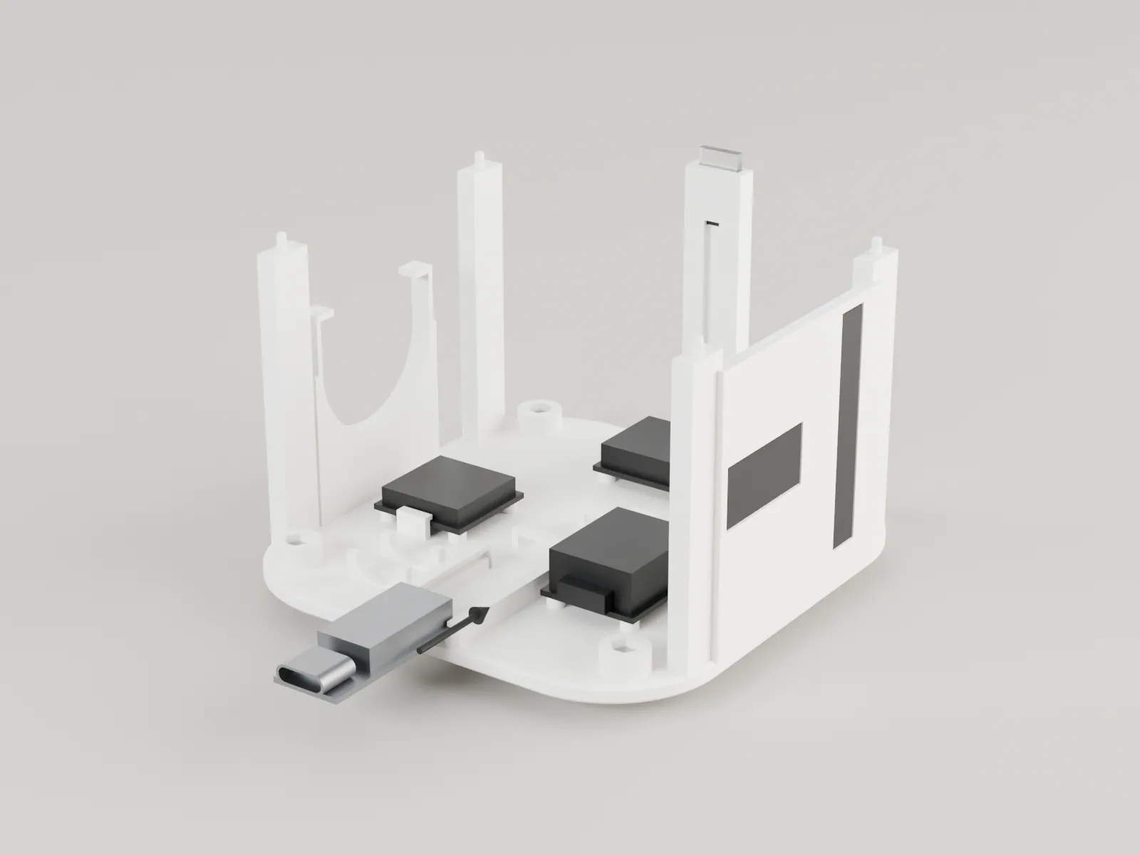
Slide the board into its rails from the back, receptacle last, until the PCB front edge meets the two stops. The stops take the plug force and the rail lips hold it down. With no shell, a dot of glue stops it sliding back when a plug is pulled.
The USB-C receptacle faces straight out of the back.
-
09
Fit the capacitor and the star
C1, C2, D2, F1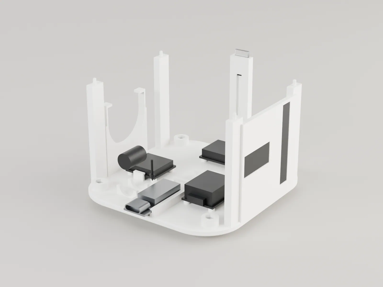
Press C1 into its two saddles beside the PD board. Its leads are the star: C2 and D2 are soldered across them, W1 (through F1) and W2 come in from the PD board, W3 to W6 go out.
C1 and D2 polarity: minus and the TVS band on the correct leads.
-
10
Fit the speaker
28 mm speaker, foam seal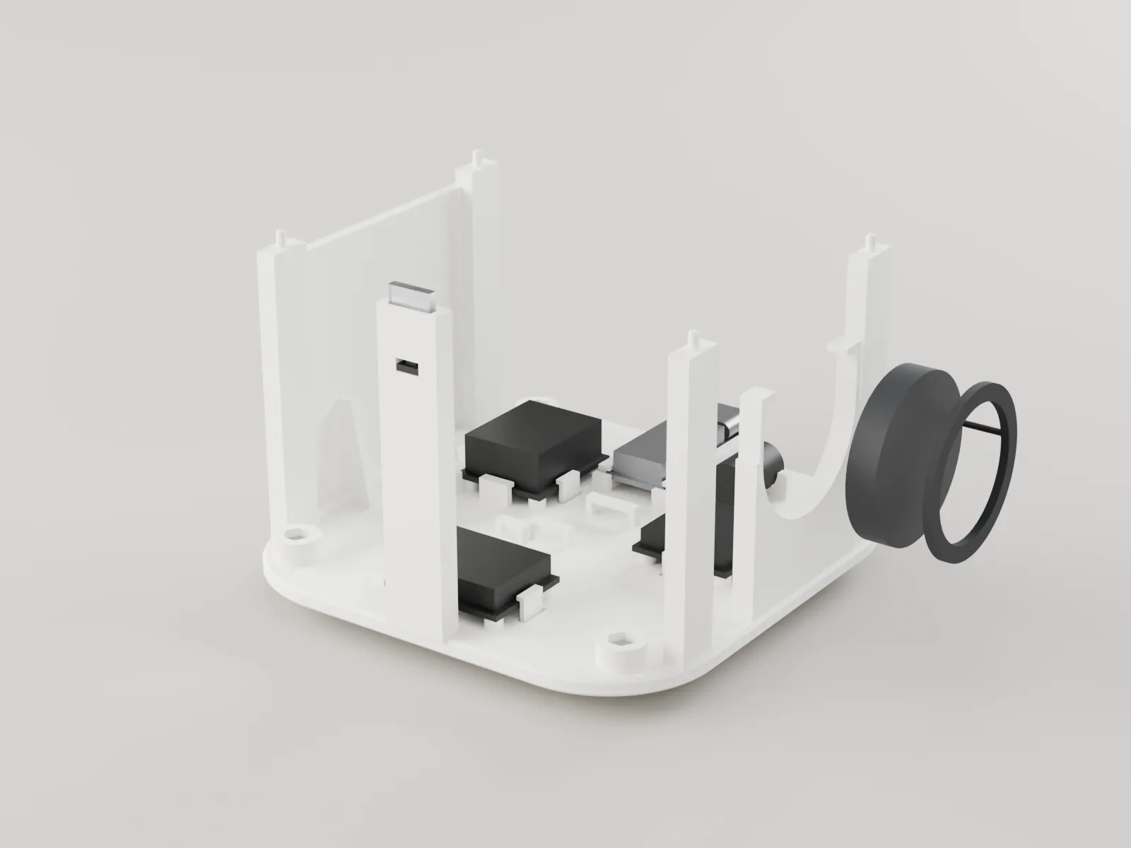
Glue the speaker on the cradle seat, sliding it in from the right until its face is flush with the cradle side. Stick the foam seal ring on the face; a shell's grille wall presses on it.
-
11
Route and tie the wiring
W1 to W19, ties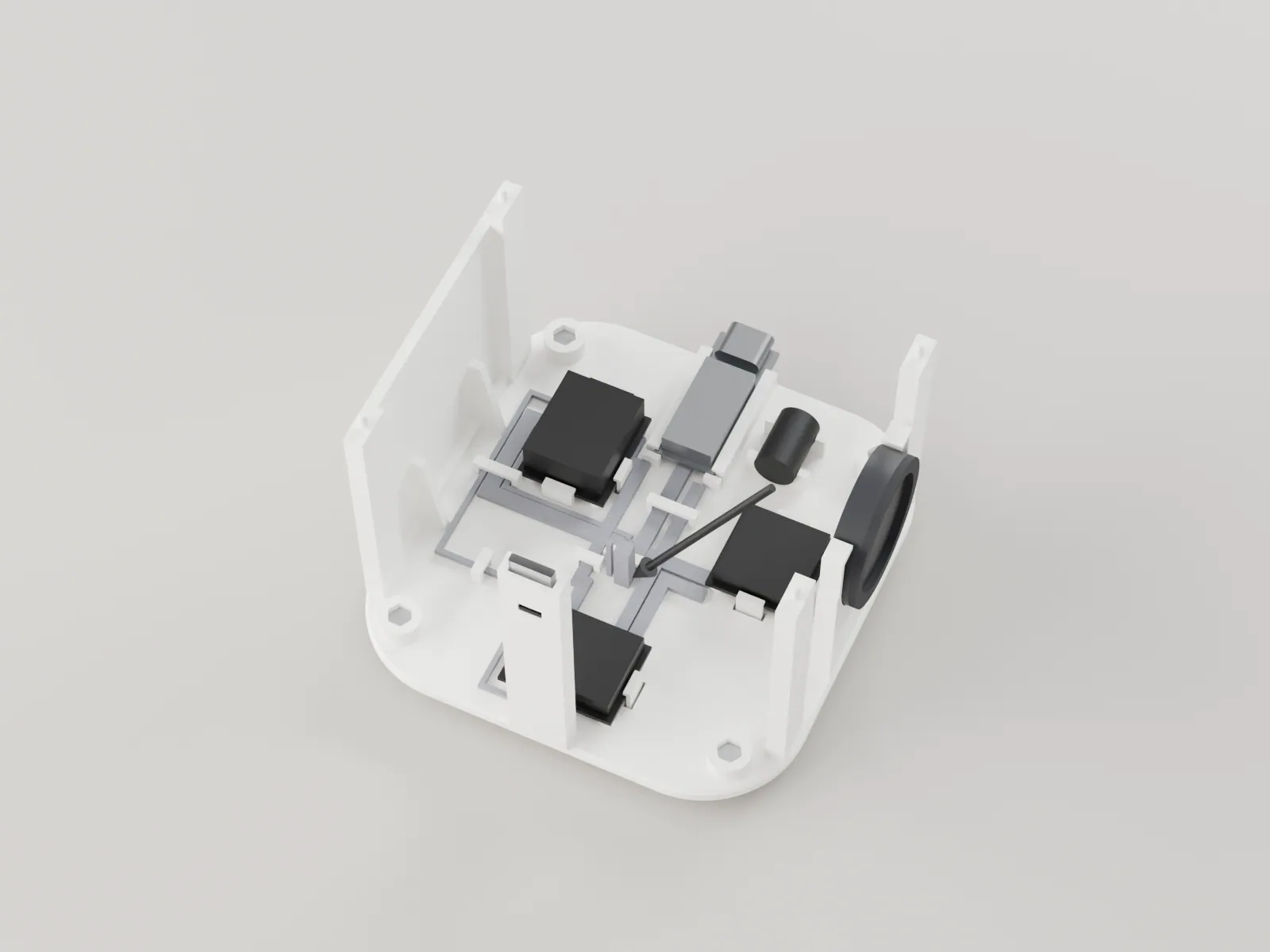
Run each bundle on the floor and tie it at the anchors: 9 V pairs beside the PD board, the printer pairs (W3, W4, W11) up into the cable room at the front, the speaker pair at the cradle. Signals leave the XIAO's left column in one lane between the XIAO and the fin (data nearest, then I2S, then LED), tied at the anchor at its front end. The 5 V pair rises beside the XIAO's right edge; its last 8 mm to the 5V pad is a free lead. Leave a 20 mm service loop at the printer harness.
No wire crosses the refill path or the XIAO's USB-C plug path.
-
12
Press on the printer adapter
printer adapter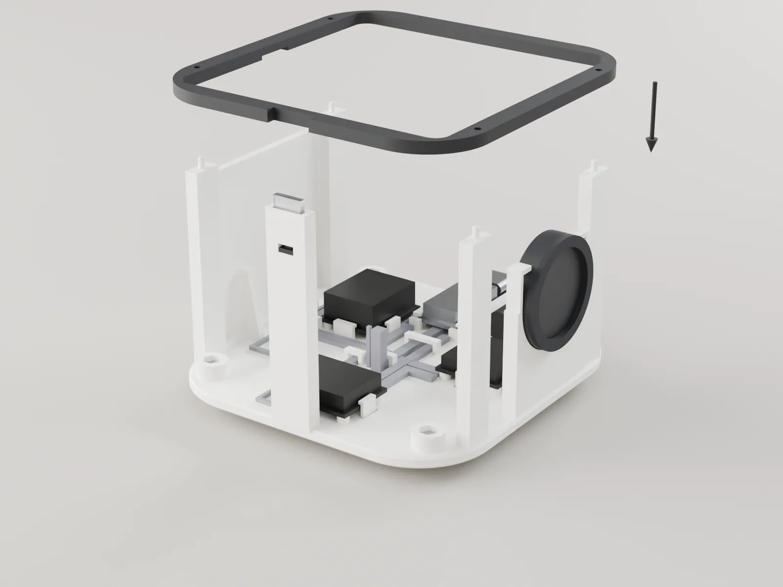
Press the adapter ring onto the four pins on the post tops until it rests on the posts, notch to the front round the light column. It is a firm slip fit; if the pin coupon showed it loose, a dot of glue on two pins.
The ring sits flat on all four posts (the fit was set by the adapter pin coupon).
-
13
Lower in the printer
thermal printer, J1, J2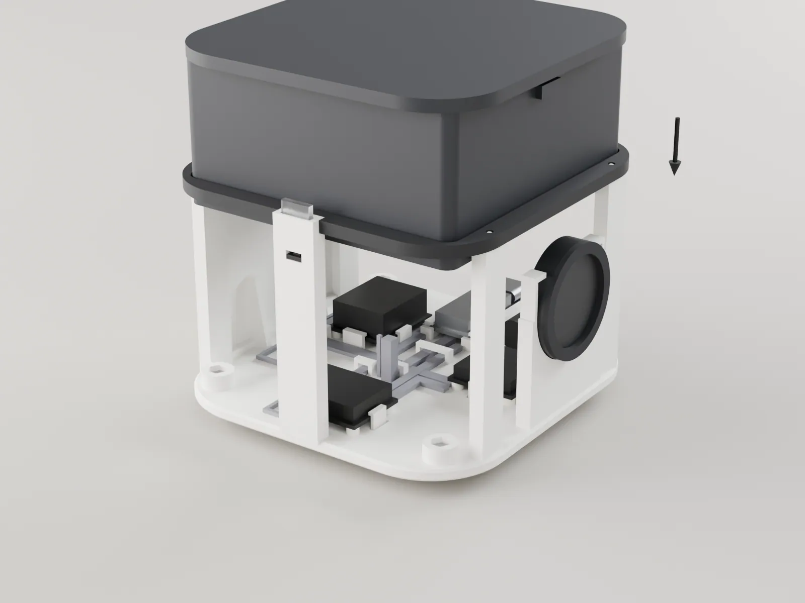
Plug J1 and J2 into the printer's leads. Lower the printer straight down through the adapter until the bezel sits on it and both side clips click under the lands. If your printer has ears instead of clips: two M2 x 6 through the bezel flange into the adapter bosses, from above.
Both clips latched, no rock, the service loop free below.
-
14
Load the paper
57 x 40 roll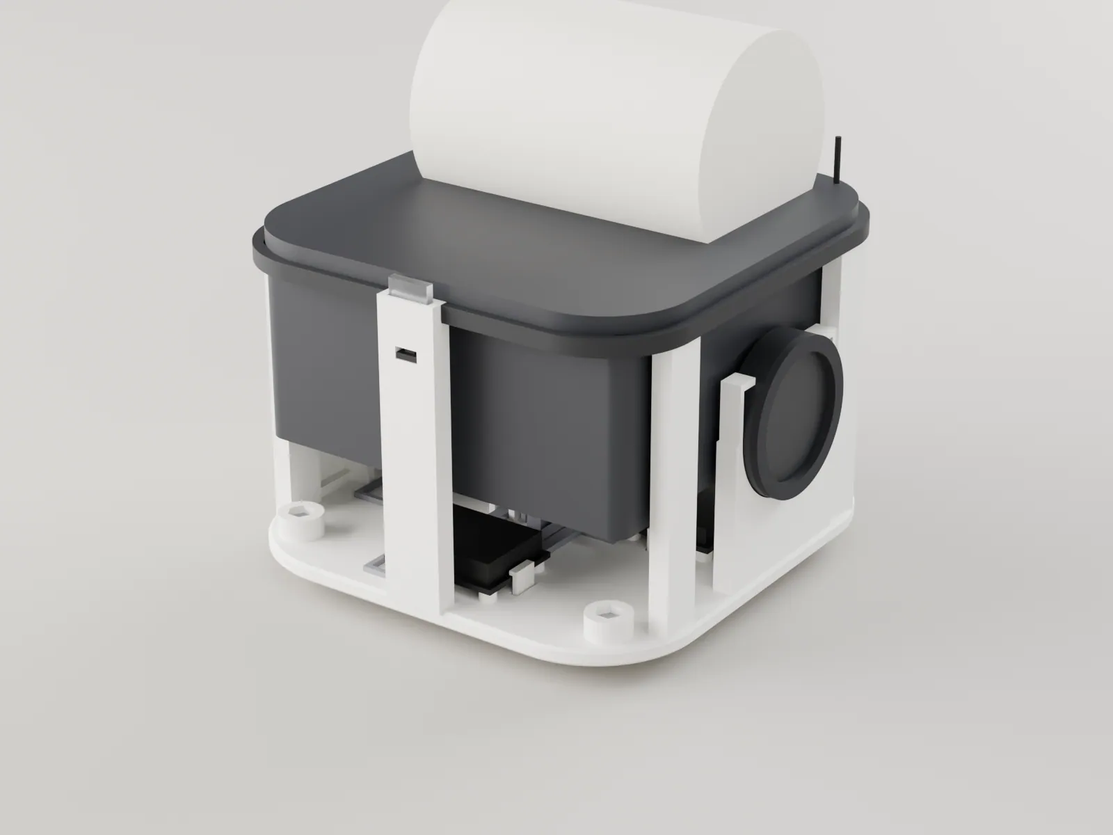
Open the printer door, drop a roll in from above with the paper end toward the front, and close the door with the paper out through the slot.
-
15
Screw on the bench base
bench base, 4 x M2 x 10Stand the core on the bench base over the four holes, the cut-out at the back under the USB-C port. From below, drive four M2 x 10 button head screws up through the base into the corner bosses. Snug, not tight.
The screw heads sit inside the feet height; the core does not rock.
-
16
Test it
PD charger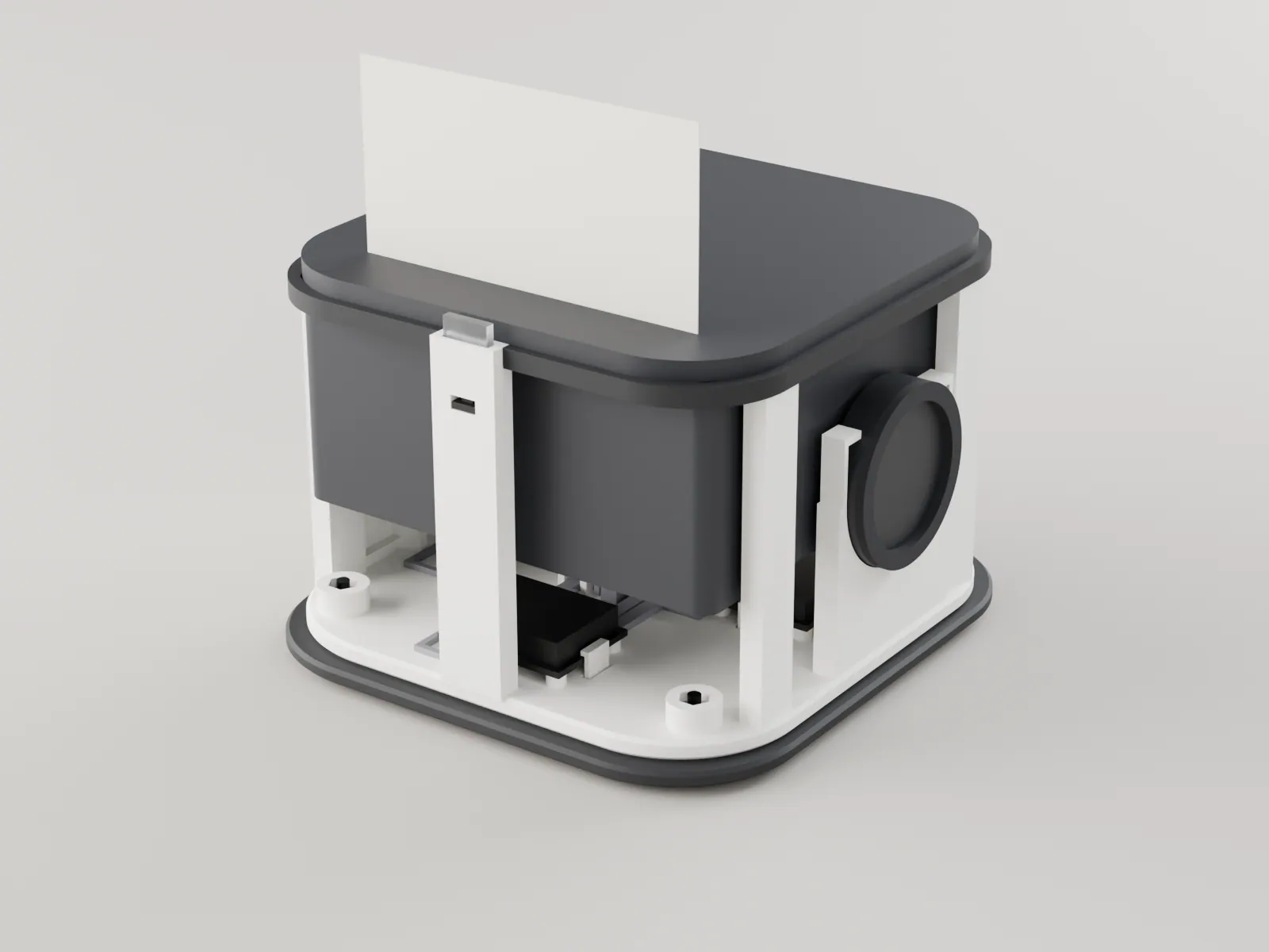
Plug a 9 V PD charger into the back port. Run
selftest, check the light, the chirp and a slip, then do the soak in bring-up step 12.The brownout count in
poweris still 0 after the soak.
Printer out: press both clips in from the sides and lift. A different printer needs only a new adapter: pull the old one off the pins. Reflash: the XIAO's USB-C faces the back with a clear plug path under the roll. PD board: slides out backwards through the bench base cut-out. Refills never need the core opened.
Skip step 15 and go on to section 11: the core slides back into the shell's band, four M2 x 8 hold it from below, and the deck and lid close over it. Another shell takes the same four screws at the length its floor needs.
Which screw goes where
| Fastener | Qty | Where | Driven | Step |
|---|---|---|---|---|
| M2 x 10 button head, ISO 7380 | 4 | bench base (or shell floor) up into the four corner bosses, at 32 and 33.5 from the centre | from below, 1.3 mm hex | 15 |
| Resin chassis: M2 hex nut, AF 4.0 x 1.6 | 4 | captive in the hex wells of the corner bosses; the screws above thread into them | dropped in, a dot of glue | 01 |
| PLA chassis: M2 heat-set insert | 4 | in the corner boss holes (3.2 dia x 4 deep), flush with the seat face | pressed with the iron, from below | 01 |
| M2 x 6 | 2 | only for a printer with ears: through the bezel flange into the adapter bosses | from above | 13 |
| Base shell (section 11) | ||||
| M2 x 8 button head, ISO 7380 | 4 | up through the band floor (head in the counterbore under each bumper recess) into the four corner bosses; replaces the M2 x 10 of the bench base | from below, 1.3 mm hex | S6 |
| M2 x 6 button head, thread-forming | 6 | through the band wall into the bosses on the deck skirt: two on the front (x +-18), two on each side (y +-24), at 10.5 above the desk | from the side, 1.3 mm hex | S9 |
Screw length rule: the tip must pass the nut or insert by 1 mm. For a floor thicker than 2.5 mm, add the difference to the length. The base shell's band clamps only 1.2 under the seat, so an M2 x 8 passes the nut by 1.2 and the insert by 2.8; an M2 x 10 would stand 1.8 above the boss top. The band screws cut their own thread in a 1.6 pilot: drive them gently and stop when the head seats on its spot face. Keep 2 spare nuts or inserts.
Exterior shell
The Pigeon base shell is three printed parts round the core: a band that is the floor and the lower wall, a deck with the paper slot, the tear trim, the light and the grille, and a lid that lifts off for paper. The core slides into the band, the deck drops over it, ten screws hold the lot and eight magnets hold the lid. Build the core first (section 09, steps 01 to 14, not the bench base) and pass bring-up.
-
S1
Print the band, deck and lid
PN84_p5_band, deck, lid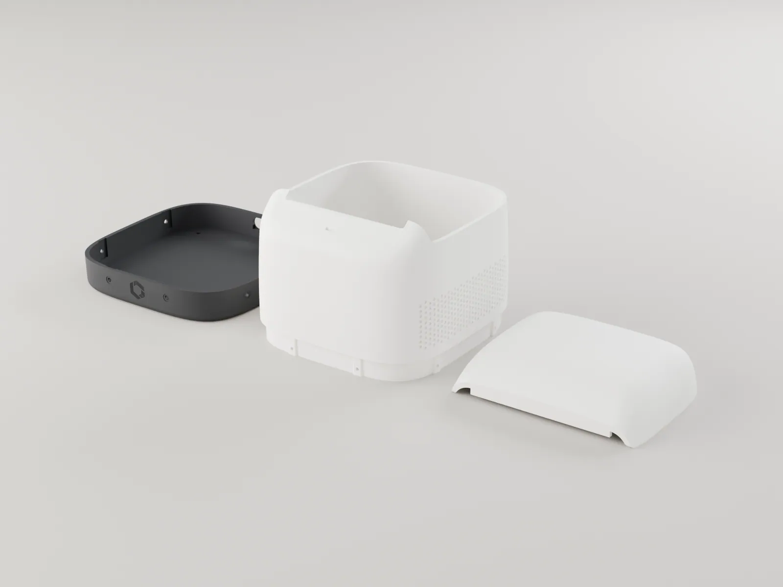
Print them as section 04 says: the deck and lid in your colourway, the band in the band colour. Clear the supports from the inside; the outside should need no sanding. Try the fit before anything goes in: the skirt round the deck's lower edge drops into the band, and the lid sits on the deck behind the slot.
The deck sits down on the band with an even 0.65 seam all round and does not rock. The lid lifts off and goes back on straight.
-
S2
Fit the tear trim
tear trim, CA glue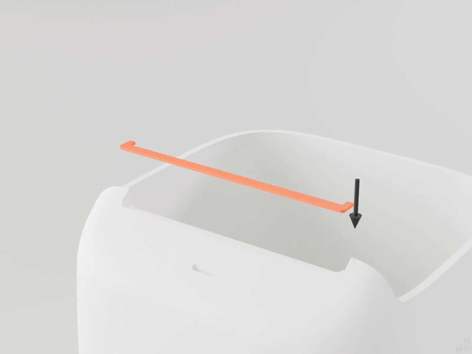
The orange trim drops into the 0.7 deep pocket round the front and both ends of the slot, toothed edge toward the slot. Put a few small dots of CA glue in the pocket, never on the teeth, and press the trim flat.
The trim is flush with the bay floor, the teeth run straight along the slot edge, and a strip of paper slides out past them without catching.
-
S3
Fit the light lens
light lens, UV resin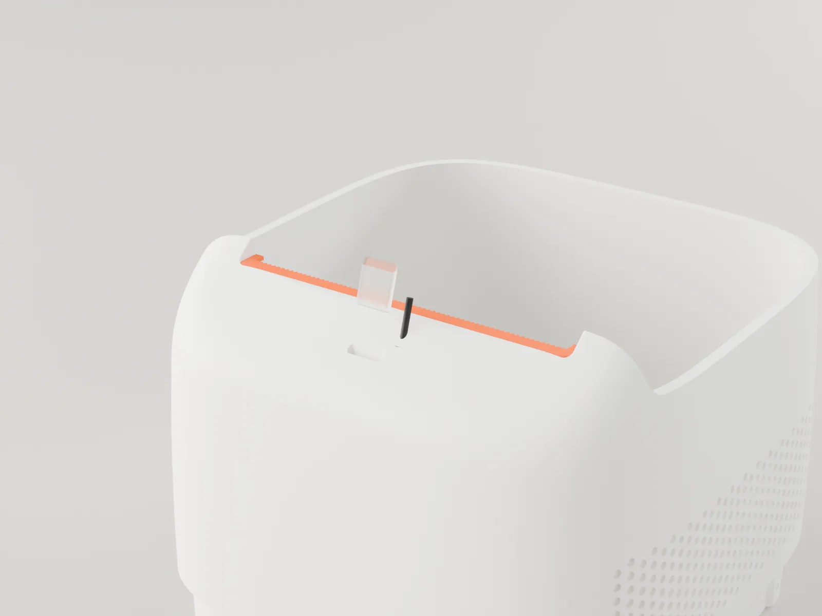
Push the clear lens into the pill-shaped hole in the front slope from outside. The hole leans back toward the light port inside, so push along it, not square to the skin. Stop when its face is flush with the deck, then hold it with a touch of clear UV resin round the inside end.
From outside the lens face is flush, not sunk or proud. From inside, its lower end points down at where the core's light port will be.
-
S4
Press in the lid and deck magnets
8 x N35 disc 5 x 2, CA glueEight N35 disc magnets, 5 x 2 mm, hold the lid on: four go in the lid bosses, pressed in from above, and four in the deck rim bosses, pressed in from below. Do the deck now, before it goes on the band. Each is a press fit plus a drop of CA glue. Polarity matters. Stack the magnets and mark the top face of each with a marker, so every marked face is the same pole. Press every lid magnet in with the marked face down and every deck magnet with the marked face up, so each pair attracts.
Each magnet sits fully in its bore with the glue dry. Hold the lid just above the deck: all four pairs pull together and none pushes away.
-
S5
Slide the core into the band
the finished core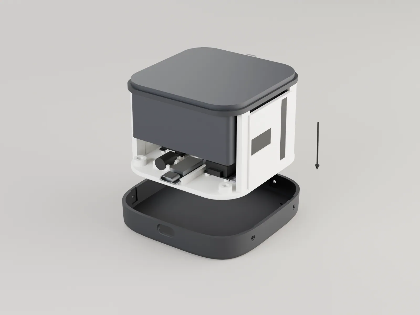
Lower the finished core into the band about 1.5 mm forward of its seat, so the USB-C nose clears the back wall. Then slide it back: the USB-C nose enters the pill opening in the back of the band, and the end of the PD board drops into its pocket inside.
The core sits flat on the floor, the four boss holes over the four floor holes, and the USB-C port is centred in the pill opening.
-
S6
Screw the core to the band
4 x M2 x 8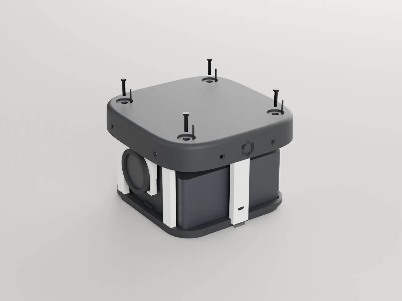
Turn the band over on a soft cloth, holding the core in. Through each bumper recess, drive an M2 x 8 button head screw up through the floor into the corner boss. Snug, not tight: the floor under the head is only 1.2 thick.
Each head sits inside its counterbore, below the floor of its recess, so a bumper will lie flat over it.
-
S7
Stick on the bumpers
4 x bumper, 10 x 3.5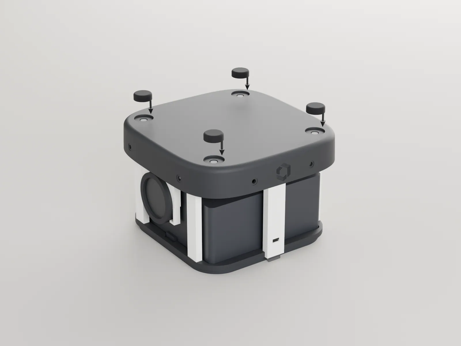
Wipe the four recesses with alcohol and let them dry. Press a bumper into each one, centred over the screw head, and hold it for a few seconds.
Stood on the desk, it does not rock and no screw head shows.
-
S8
Lower the deck onto the band
deck with trim and lens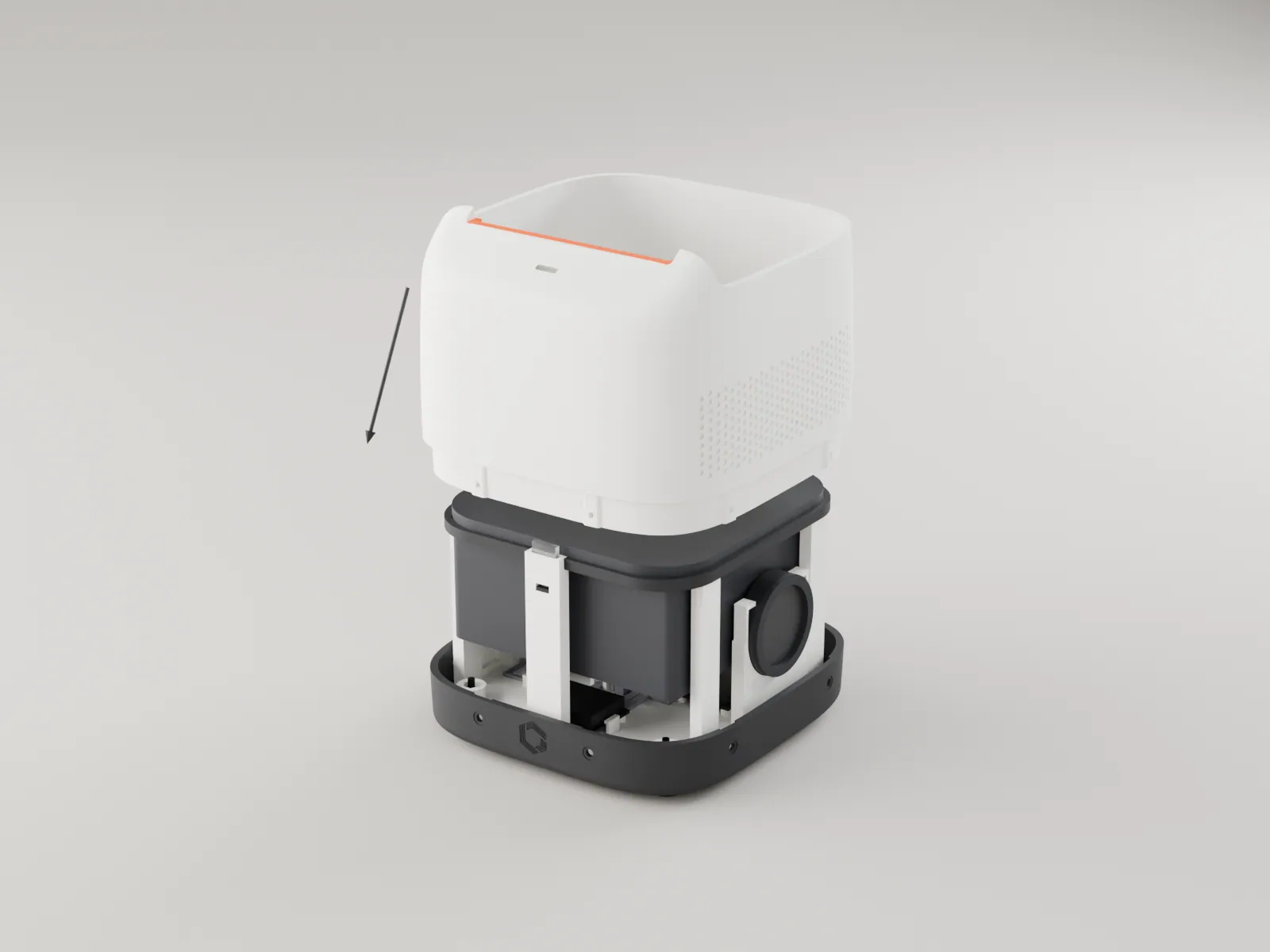
Turn it upright. Lower the deck straight down over the core, slot to the front and grille to the right: the skirt round its lower edge drops inside the band and locates it. Nothing needs force; if it stops, lift it and look rather than push.
The seam is an even 0.65 all round, the six holes in the band line up with the bosses on the skirt, and the grille sits over the speaker.
-
S9
Fix the deck with six screws
6 x M2 x 6, thread-forming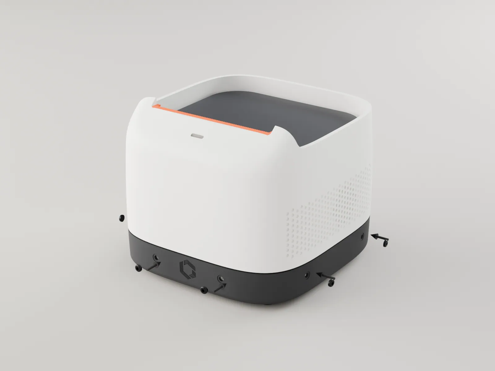
Drive the six screws through the band wall into the skirt bosses: two at the front, two on each side. They cut their own thread, so the first turns are stiff. Go gently and stop as soon as each head seats on its spot face; over-driving strips the printed thread.
All six heads sit flat on their spot faces, and the seam does not open or pinch near any screw.
-
S10
Set the lid on
lid, PD charger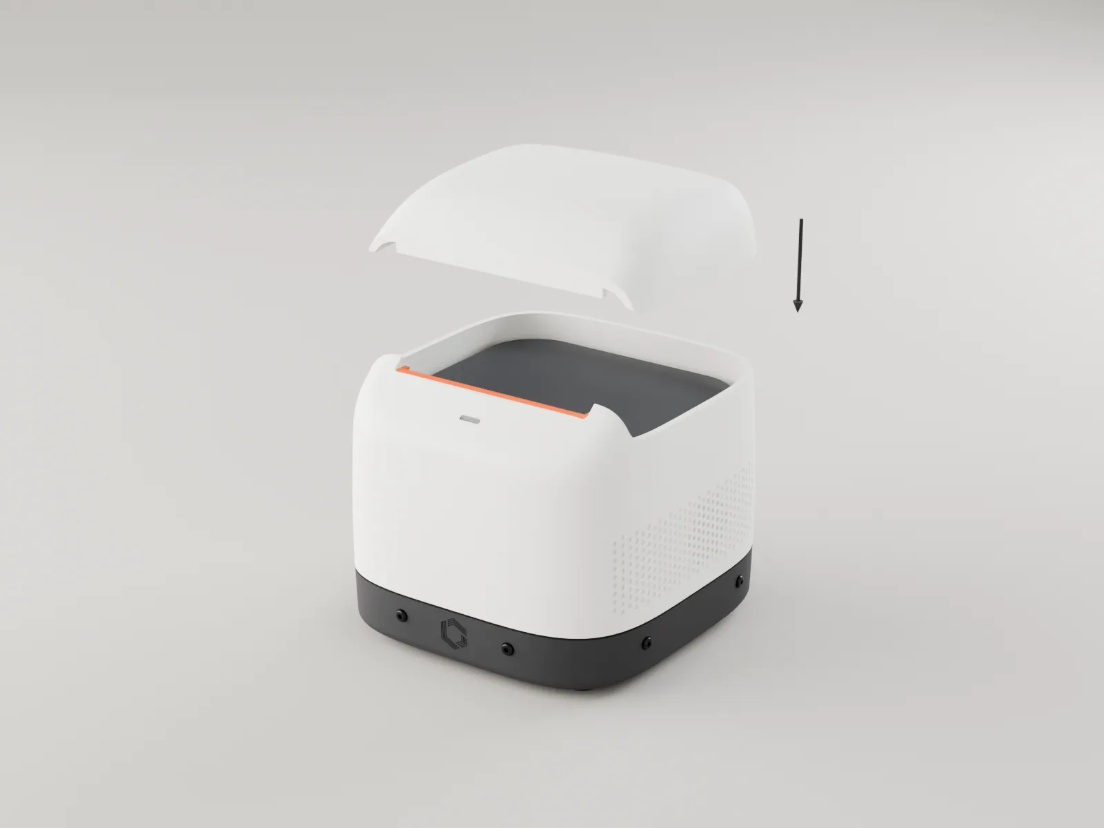
Set the lid on the deck behind the slot. The two tapered pins at its front corners seat in sockets in the deck, so the lid fits one way only, and the four magnets then draw it down onto the seam. To change the roll, pinch the lid by its sides and lift it straight off. Plug a 9 V PD charger into the back port and run
selftest: the slip comes up through the slot past the trim.The pins seat and the lid pulls down by itself; its front edge meets the back of the slot with no gap, the light glows through the lens, and a test slip tears cleanly on the teeth.
Paper: pinch the lid by its sides and lift it off the magnets. Anything else: take the six band screws out and lift the deck straight up; the core stays in the band. To take the core out, peel the bumpers, remove the four floor screws and slide the core forward 1.5 before lifting it, so the USB-C nose clears the pill.
Both antennas are on the core's left side. The left band screws sit just behind and in front of the antenna zone; do not add metal (paint, tape, extra screws) to the left face of the shell. The left lid magnet and the left band screws sit near this zone, so check them in the radio test.
For community shells: the interface
what any shell must meetAny shell that meets the interface below fits the core with no change to it. The base shell above is one example.
Envelope and seat
mm| Point | Requirement |
|---|---|
| Hard box | 85 x 87 in plan, R 20 corners, from the seat plane to the printer face (59 tall). Keep 1 clear everywhere except where the shell meets the core on purpose |
| I1 Seat | flat floor under the 84 x 86 plate (R 19.5). Reference: seat plane 4 above the desk (feet 1.5 + floor 2.5) |
| I2 Fixing | four 2.3 holes at x +-32, y +-33.5; M2 x 10 up from below for a 2.5 floor |
| I3 Paper exit | slot at least 59.5 x 2.5, centred on x 0, y -28.5, at the printer face; paper rises vertically |
| I4 USB-C | opening at least 9.4 x 3.7 on the back, centre z 11.65 in the reference placement; a notch open to the lower edge, since the nose stands 5 past the box |
Light, sound, refill
mm| Point | Requirement |
|---|---|
| I5 Light | lens over the 7.8 x 1.6 light port at x 0, y -41.85, starting within 1 above it |
| I6 Speaker | grille wall 1.4 to 1.8 from the speaker face on the right side, over the foam ring; open pattern inside radius 10.6 |
| I7 Refill | a removable lid over the door; with it off, the space over the door to 70 above the face is free. Anything that stays on ends in front of y -27.5 |
| I9 Heat | print head about 6 W peak under the exit; let warm air leave high at the back and enter low. No fan needed |
| I10 Antennas | both FPCs on the left fin (x -42, y +-23.5, up to z 54). No metal (paint, inserts, magnets, screws) within 10 of the left side between y -23.5 and 23.5 |
Frame: +x to the right seen from the front, +y to the back (the USB-C side), origin on the vertical centre line. The full interface, with every figure and the core's extents per height, is cad/INTERFACE.md. Positions are fixed; sizes of bought parts are nominal until measured.
Sending messages
The PN-84 prints only messages from its contacts. Messages are Nostr private direct messages (NIP-17), sealed and gift wrapped (NIP-59) and encrypted with NIP-44, sent through public relays (wss://nos.lol and wss://relay.primal.net by default). Relays see the recipient, the size and the time, never the sender or the text.
From a browser
the web sender- Open the web sender page. It makes a sender key in your browser and shows your sender npub.
- Become a contact. Give the npub to the printer's owner, who adds you with a short display id (the page shows the exact command):
contact add <your npub> ABC-1 - Enter the printer's npub (the owner reads it with
idor from the setup page), write the message and press Send. - Read the relay list. One relay returning OK is enough. It means the relay has the message, not that it has printed.
Manage key: export the nsec to keep it, import one, or use a NIP-07 browser extension that supports NIP-44. The key lives in the browser's local storage; treat it as a low-value identity used only for this.
From the printer and the command line
USB console, rc-cli# on the printer's USB console
id # this printer's npub, Wi-Fi, relays
contact add npub1... KESTREL-7 rc
send KESTREL-7 hello back # reply to a contact
pending # senders waiting for approval
contact approve KEY ID # their next message prints
# from a computer, with resilient-comms rc-cli
rc-cli send --peer <printer hex from id> \
--relays "wss://nos.lol,wss://relay.primal.net" "hello"A valid message from a key that is not a contact never prints. The sender is held as pending with a 40 character preview, for the owner to approve or dismiss in the admin page (portal) or over USB. Approving does not print the held message; the sender's next one prints.
Sender and recipient display ids, a serial number, the local time and the path (internet or radio), then the message. Wording and layout depend on the voice the firmware was built with.
Troubleshooting
| Symptom | Likely cause | Fix |
|---|---|---|
| Printing | ||
| Nothing prints, no setup slip | baud rate differs from 9600 | baudscan; the clean number is the rate; baud N. Or hold FEED at power-up for the printer's own self-test, which lists its rate |
| Garbled slips | 3.3 V data not read reliably, or a ground issue | fit W12 (TTL ground) first; if still garbled, a 3.3 to 5 V level shifter in W11 |
| A stray character or feed after each reset | D4 floats during boot | fit R2, 10 kohm from D4 to 3V3 |
| Printer restarts in the middle of a slip | the charger cut out on a current peak | use a charger with 9 V at 2 A or more; keep heat auto; check power for brownouts |
| Faint or streaky print | heat time and density not tuned | sweep, then heat and density (bring-up step 8) |
| The last line does not clear the tear edge | tail feed too short | feed 5 to check, then set the tail feed in config.h |
| Power | ||
| PD trigger reads above 9.45 V | wrong trigger setting or a misnegotiation | stop; do not connect the printer. Replace or re-set the trigger |
| More than 0.5 V of sag during the burst test | not enough local capacitance | add a second 470 uF at J1 in the cable room |
| Supply goes into its limit at power-on | a short or a reversed part | power off; check C1 and D2 polarity and every W end to end. Never raise the limit |
| Network | ||
| A message does not print | sender is not a contact, or the printer reads other relays | pending to see held senders; check both sides use a common relay; id shows relay states |
| Phone will not join from the setup QR | slip lost or the QR too small to read | setup prints it again; portal reset restarts setup |
| Board not found for flashing | not in download mode | hold BOOT, press and release RESET, release BOOT |
| No USB console after flashing | USB CDC On Boot disabled in the build | keep the board defaults; the sketch refuses to build with it off |
lora probe fails | the kit's pins differ from config.h | stop and fix the LoRa pins before anything else |
| Fit | ||
| Printer will not clip in, or rocks | clip land thickness | reprint coupon_clip_land, set PANEL_T, reprint the adapter only. Ears printer: M2 x 6 from above |
| Nut turns in its well, or insert goes in crooked | pocket size | reprint the nut or heat-set coupon and set the winning size before the chassis |
| PD board slides back when unplugging | no shell to stop it | a dot of glue at the rail |
Licence and credits
| What | Licence |
|---|---|
| Hardware: core chassis, printer adapter, bench base, light pipe, interface files, electrical reference. Changes to the core stay open; shells that only connect through the interface choose their own licence | CERN-OHL-W-2.0 |
| Firmware: the sketch and its libraries in the repository | Apache-2.0 |
| Third-party parts of the firmware keep their own terms: libsecp256k1 (MIT), libsodium (ISC), cJSON (MIT), ESP-IDF components (Apache-2.0), arduino-esp32 core (LGPL-2.1) | their own licences |
| Web sender: the sender page (nostr-tools is Unlicense, its noble libraries MIT) | Apache-2.0 |
| Documentation: this manual and its images, the spec, wiring and parts lists. Code samples in the docs are Apache-2.0 | CC BY-SA 4.0 |
| Fonts embedded in this page: Inter, IBM Plex Mono | SIL Open Font License 1.1 |
Pigeon and PN-84 are names used by Reactive Pixels and are not licensed by the above. Compatible devices may say they are based on or compatible with the open platform, but may not use these names as their own branding. Paper rolls are generic and are never sold under the Pigeon name.
© 2026 Rod Leviton, RPXL / Reactive Pixels. The PN-84 page and the rest of the range: Pigeon. More from the studio at reactivepixels.com.