ShortwaveHandheld walkie
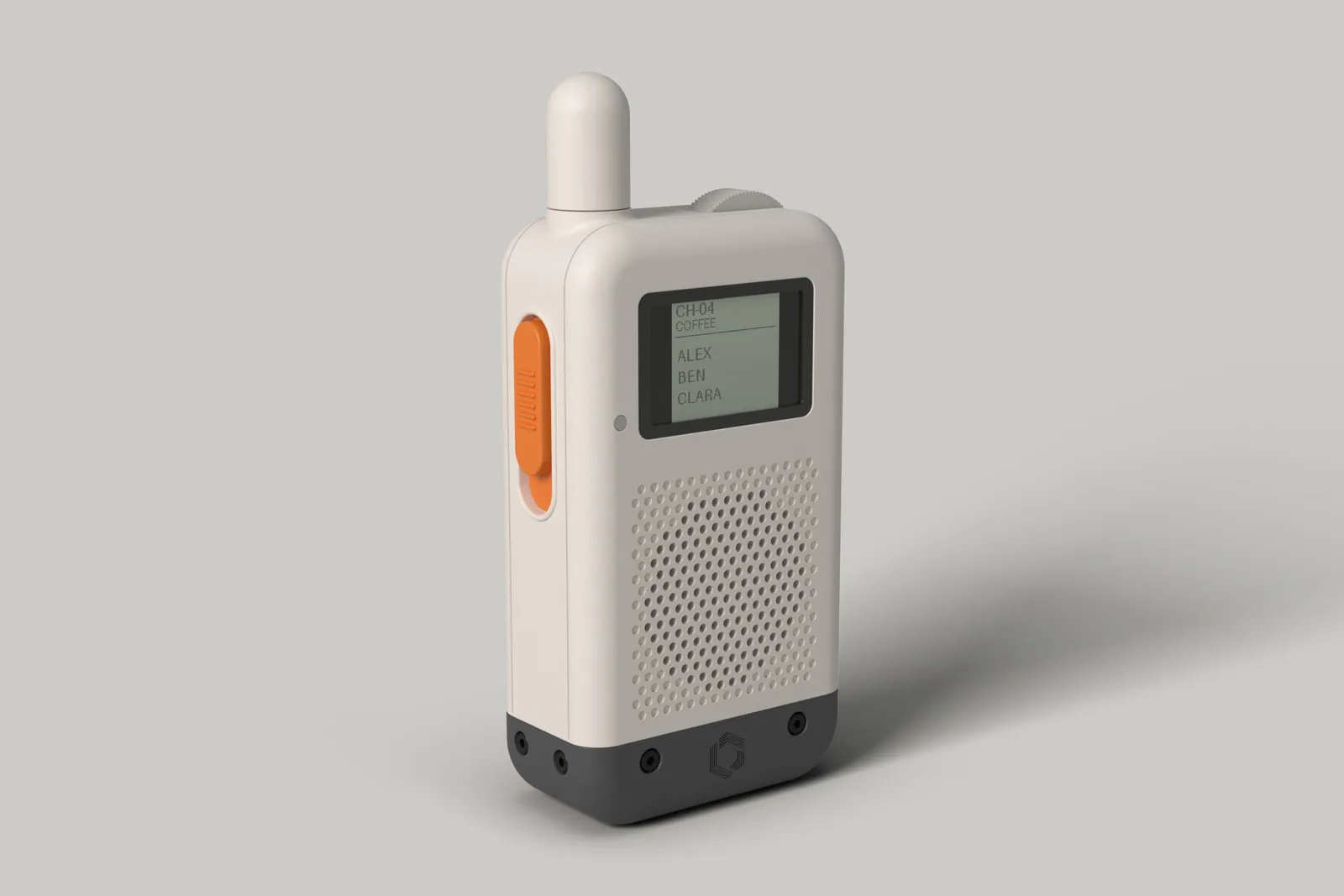
Hold the button, talk, let go: your mate hears you on their own handset, not on your phone. Shortwave is a physical handheld with a screen, a channel wheel, a talk key and a real external antenna. Wi-Fi comes first, and a LoRa radio keeps a link when the internet does not. You print it and build it by hand. This draft covers the hardware; the firmware is not written yet.
- Size
- 58 x 104mm, 30 deep, antenna 24 above
- Radio
- LoRa 915SX1262, real SMA antenna
- Screen
- Memory LCDSharp LS013B7DH03, 128 x 128
- Controller
- ESP32-S3XIAO + Wio-SX1262
- Battery
- 1000 mAhabout 7 days standby, 2.8 h of play, estimates
- Parts
- A$125about, per unit, before tools
The casing and the core are designed and drawn (build c2, resin) but not printed. The core parts are not bench-fitted: check each on arrival. The firmware is not written. Sizes of bought parts are nominal until measured.
What you're building
A handheld walkie-talkie for you and your mates, not your phone. Hold the button, talk, let go: your mate hears it on their own handset. Every Shortwave handset is a core and a casing. The core does all the work and stands on its own; the casing is what you see, and meets the core only at a small documented interface, so anyone can build a different case around the same core.
Layer 1: the core
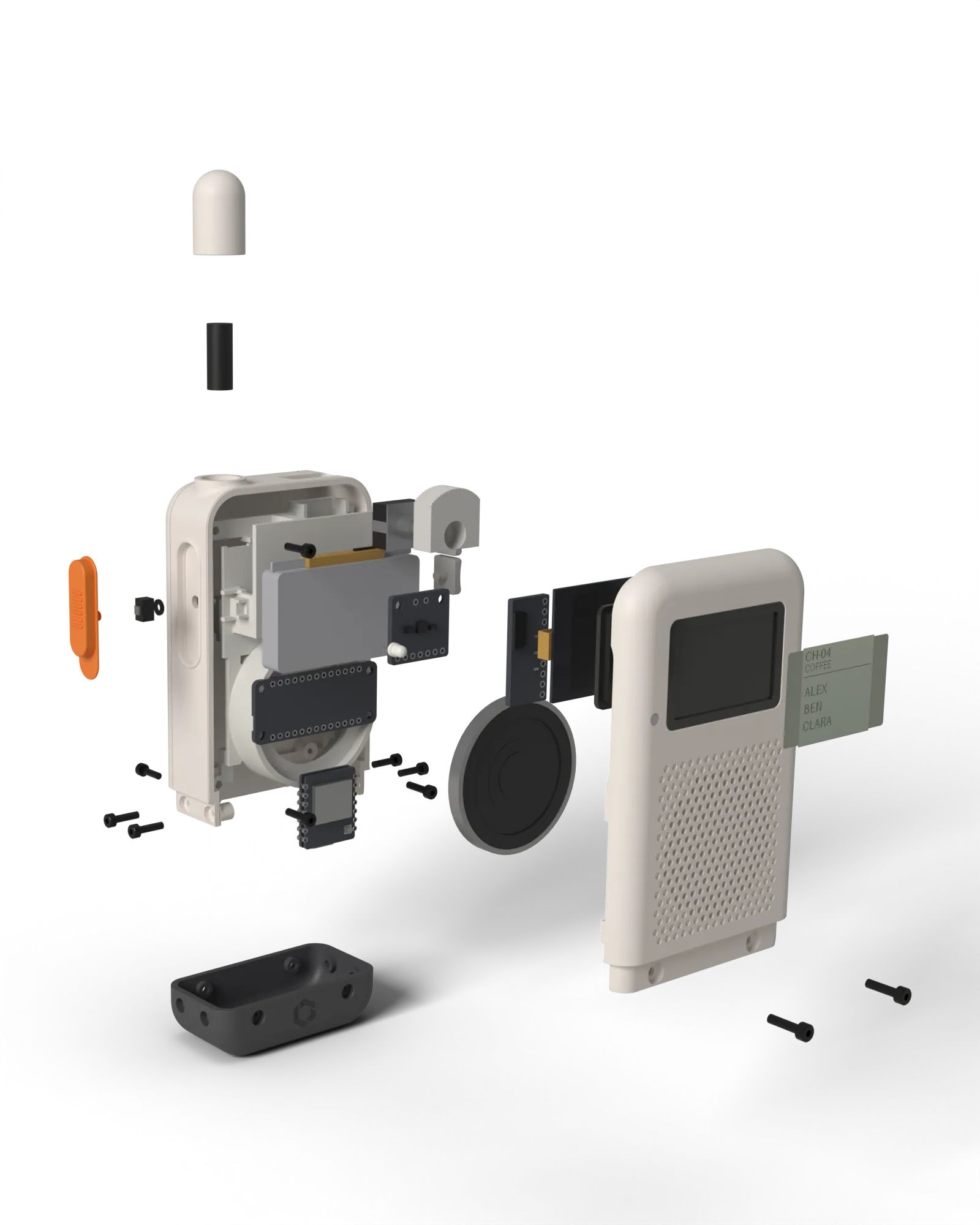
platformA controller with Wi-Fi and a LoRa radio, a memory screen (3.3 V, no boost board), a 40 mm speaker, a microphone, a battery, a talk key, a volume rocker, a channel wheel, a status light, USB-C and a real external SMA antenna, all bought modules wired together and held in one printed cradle. No custom circuit board.
- The core works with no case.
- Four M2 screws hold it to the casing.
- USB-C on the base, antenna on top, keys on the sides.
Layer 2: the casing
shellThe Classic casing: a lid and a tub that snap together, a charcoal band held by eight cap screws, a window with bezel and glass, a clear status light, a talk key and two volume rockers that fit from outside and are held by a small flexible ring inside, a wheel, and an antenna boot with a fine seam line. Sixteen printed parts, including the cradle that holds the core modules, the black LCD mask and the three key rings, and twelve screws.
- Prints in resin on an MSLA printer (the main route), or in PLA on any 0.4 mm FDM printer (the second route).
- No glue is needed except, perhaps, for the bezel.
- No captive nuts and no heat-set inserts.
Draft. The casing and the core are designed and drawn (build c2, resin) but nothing has been printed or fitted yet. The core parts are bought but not bench-fitted: every core part is marked check on arrival, and the sizes marked NOMINAL (the screen tail fold and its adapter, the speaker frame height, the encoder height) matter most. The firmware is not written (section 07).
Tools and supplies
Tools
needed- A 3D printer. Resin route: MSLA, a bed of 196 x 122 mm or larger (Saturn S 4K class). PLA route: FDM, 0.4 mm nozzle, a bed of 120 x 120 mm or larger. The biggest part, the tub, is 59 x 24 x 97 mm.
- Wash and cure kit (resin route): isopropyl alcohol, gloves and a UV cure station.
- M2 hand tap (resin route), about A$8, ESTIMATE. It threads the eight band pilots once.
- Hex key, 1.5 mm. Every screw in this build uses it.
- Soldering iron, solder, flux. A fine tip helps on the XIAO battery pads.
- 8 mm spanner, for the SMA nut.
- Multimeter, for continuity and battery polarity.
- Calipers, to check the bought parts on arrival and the first print.
- Wire strippers, flush cutters, tweezers, a heat gun or lighter for heat shrink.
- Sandpaper 400 to 800 and a hobby knife to clean print edges.
Supplies and extras
nice to have- USB-C data cable and a charger.
- Hookup wire 26 to 28 AWG, 1.5 mm heat shrink, kapton tape.
- Closed-cell foam tape, 1.0 mm, for the speaker seal and the screen pad.
- Resin (resin route): Resione Tough 74 v2, Siraya Tenacious and Tenacious Clear, Resione F69, and Elegoo ABS-Like 3.0 for the prototype run and the coupons. About 75 g of resin per handset, supports included.
- Filament (PLA route): PLA, TPU 95A for the boot and rings, clear PETG for the status light.
- Clear sheet, 0.2 mm or thinner (polycarbonate or acetate), for the window pane. It is cut, not printed.
- Cyanoacrylate glue, for the bezel (a thin bead).
- A feeler gauge or a strip of paper to look at the 0.15 mm boot seam.
Parts to buy
Prices are per unit in Australian dollars, GST included where the retailer shows it, shipping not included. LISTED means read from a retailer page. ESTIMATE means no live listing was read: a planning figure, to be checked before ordering. Small parts come in packs, so the cash for a first unit is higher than the total.
| Part | Spec | Qty | Typical source | Fallback | Checked | A$ | Basis |
|---|---|---|---|---|---|---|---|
| Core: radio and controller | |||||||
| MCU and LoRa kit | Seeed XIAO ESP32S3 and Wio-SX1262 kit (the PN-84 board), with its antennas. Stack 17.5 x 21 x 8 mm Check on arrival. | 1 | Core Electronics | none recorded | not rechecked (c1) | 21.20 | LISTED |
| LoRa antenna | TE Linx ANT-915-NUB-SMA, straight SMA stubby, 17.7 mm high, 915 MHz Check on arrival. | 1 | DigiKey | none recorded | not rechecked (c1) | 8.00 | ESTIMATE |
| LoRa pigtail | U.FL to SMA bulkhead jack pigtail (the jack goes through the top plate) Check on arrival. | 1 | generic | none recorded | not rechecked (c1) | 6.00 | ESTIMATE |
| Core: screen, audio, power | |||||||
| Screen | Sharp LS013B7DH03 memory LCD, 128 x 128, outline 26.6 x 30.3, active 23.04 square, runs on 3.3 V (VDD and VDDA 2.7 to 3.3 V). Source: DigiKey AU, 32,108 in stock. The FPC tail fold is NOMINAL Check on arrival. | 1 | DigiKey AU | none in stock at this size (the LS013B7DH05 is tray only) | 2026-11-16 | 20.13 | LISTED |
| Screen FPC adapter | 10 pin, 0.5 mm flip-ZIF to 2.54 mm adapter, dual contact. Size and contact side are NOMINAL Check on arrival. | 1 | AliExpress, eBay AU | none recorded | not rechecked (c1) | 3.00 | ESTIMATE |
| I2C expander | Adafruit 5346 MCP23017 breakout (STEMMA QT), 43 x 18 x 5 mm, carries the keys, wheel, light and screen select Check on arrival. | 1 | Core Electronics | none recorded | not rechecked (c1) | 11.25 | LISTED |
| Microphone | INMP441 I2S MEMS module, about 14 x 14 Check on arrival. | 1 | Zaitronics | none recorded | not rechecked (c1) | 7.80 | LISTED |
| Amplifier | Adafruit 3006 MAX98357A I2S class D, 19.4 x 17.8 x 3.0 Check on arrival. | 1 | Core Electronics | none recorded | not rechecked (c1) | 10.65 | LISTED |
| Speaker | PUI Audio AS04008MR-2-LWC80, 40 mm round x 5.0, 8 ohm, 2 W, wire leads. Source: DigiKey AU, 145 in stock Check on arrival. | 1 | DigiKey AU | Same Sky CMS-40558N-L152, 40 x 5.5, 8 ohm, 0.5 W: DigiKey AU, 8,506 in stock, A$9.55. The firmware caps the volume if you fit it | 2026-11-16 | 8.03 | LISTED |
| Battery | Core Electronics CE06795, LiPo 3.7 V, 1000 mAh, 7 x 30 x 50 mm, protected (PCM), with a temperature (NTC) lead. It has a 3 pin JST-PH plug: cut the plug off, solder the red and black leads to the XIAO battery pads and insulate the third (NTC) lead Check on arrival. | 1 | Core Electronics (in stock) | Tempero Systems 703048, 1000 mAh, 6.6 x 29 x 49: search text says 50 in stock but the page could not be read. Confirm before ordering. Battery has one live source: RISK | 2026-11-16 | 8.50 | LISTED |
| Battery divider and screen parts | 2 x 220 kohm and 100 nF on the battery sense; 1 uF on the screen VDD and 0.1 uF on VDDA and on DISP; 2 x 10 kohm pull-downs Check on arrival. | 1 set | any | none recorded | not rechecked (c1) | 0.70 | ESTIMATE |
| Core: controls and light | |||||||
| Wheel encoder | Bourns PEC11R-4215F-S0024, 6 mm D shaft, push switch, 24 detents, body 13.4 x 12.5, M7 x 0.75 bushing 5.0 long (the wheel is relieved to take the bushing). The height with the switch (7.0) is NOMINAL. Source: DigiKey AU, 11,616 in stock Check on arrival. | 1 | DigiKey AU | Alps EC11E15244B2: DigiKey AU, 817 in stock, A$8.12. Its bushing is 7.0 long, so the wheel relief needs to be deeper (not modelled) | 2026-11-16 | 4.80 | LISTED |
| Side switches | right-angle (side-push) through-hole tact switches, about 4.5 x 6 x 3.5 Check on arrival. | 3 | generic | none recorded | not rechecked (c1) | 1.50 | ESTIMATE |
| Status LED | 3 mm LED and a 330 ohm resistor Check on arrival. | 1 | generic | none recorded | not rechecked (c1) | 0.30 | ESTIMATE |
| Fixings and supplies | |||||||
| Wiring | JST-PH pigtails, hookup wire, heat shrink | 1 set | any | none recorded | not rechecked (c1) | 5.00 | ESTIMATE |
| M2 x 8 screw | ISO 4762 hex socket cap screw, black, M2 x 8 (1.5 mm hex). 12 per handset: 8 band, 4 core. The reference build used an existing assortment kit (A$0); priced here as bought singly | 12 | Bunnings, AliExpress | none recorded | not rechecked (c1) | 1.44 | ESTIMATE |
| Printing material, resin route | |||||||
| Resione Tough 74 v2 | Tub, band, wheel, bezel, cradle, mic seat, LCD mask, talk key and rockers. Prints grey. About 75 g of resin per handset in all four resins, supports included, valued here at the Tough 74 v2 price of about A$95 per kg. If you already own the resin it costs nothing extra | about 0.075 kg | any resin retailer | any tough, rigid grey resin that passes the coupons | not rechecked (c1) | 7.00 | ESTIMATE |
| Siraya Tenacious | Lid, which carries the two snap hooks. Counted in the line above | 1 part | any resin retailer | none recorded | not rechecked (c1) | 0.00 | in line above |
| Siraya Tenacious Clear | Status light. Counted in the line above | 1 part | any resin retailer | none recorded | not rechecked (c1) | 0.00 | in line above |
| Resione F69 | Flexible resin for the antenna boot and the three key rings. Counted in the line above | 4 parts | any resin retailer | none recorded | not rechecked (c1) | 0.00 | in line above |
| Primer and paint | Spray primer, warm white, charcoal, orange and black paint, clear coat (the Finish section). Small cans, one set per handset or a few handsets | 1 set | any hobby or hardware shop | none recorded | not rechecked (c1) | 0.00 | not priced |
| Total | per handset, as priced above (resin route) | 125.30 | sum of the lines above | ||||
About A$125 per handset on the resin route (A$125.30 as priced above). The five c2 core parts (screen, speaker, encoder, battery, and the 3.3 V screen that needs no boost board) are LISTED prices read on 2026-11-16 from stocked pages, A$ including GST. The Pololu 5 V boost (A$8.95) is gone. Prices marked ESTIMATE have not been read from a live listing. Paint is not priced. The PLA route is not priced here.
Core parts have been chosen and fitted in CAD from their listed sizes, never measured on the bench. The stock and prices of the c2 parts were read on 2026-11-16: recheck before ordering. Measure every one when it arrives and compare with the sizes in section 08. The cap screw is the only part already checked against its CAD counterbore.
The battery has one live source (Core Electronics CE06795): find a second before you order a batch. The Wio-SX1262 antenna connector is U.FL, so the pigtail above stands. Bench checks that CAD cannot do: the PUI speaker frame height (1.5 mm, NOMINAL), the PEC11R body height with its switch (7.0, NOMINAL), the real thickness and lead exit of the CE06795, and the fold of the screen tail. The encoder top back corner is 0.55 mm from the tub top wall (rule 1.0): no contact, recorded as an exception.
Print the parts
The Shortwave casing prints on two routes. Resin is the main one: an MSLA printer with a bed of 196 x 122 mm or larger (Saturn S 4K class) and a minimum wall of 1.2 mm. PLA is the second: any FDM printer with a 0.4 mm nozzle and a minimum wall of 1.6 mm. The handset looks the same either way. Pick one route and use its files. Print the coupons first, then the casing. Every route-specific file is named c2_resin_* or c2_pla_*; the print-ready copies are in cad/out/print/c2_*.
Print everything in Elegoo ABS-Like 3.0, test the fits with the coupons, then print the final parts in Tough 74 v2, F69 and Tenacious. The F69 boot cannot be prototyped in a rigid resin, so the prototype uses c2_resin_proto_antenna_boot: the same shape in ABS-Like 3.0 with a 0.1 mm press fit on the stubby, for look and fit only. This is the resin route; the PLA route prints its parts once.
What gets printed
build c2, both routesModel-frame files are cad/out/c2_resin_<part>.stl and .step, and cad/out/c2_pla_<part>.stl and .step. Print-oriented copies, already tilted as the tables below say, are in cad/out/print/ as c2_<route>_<part>_print.stl (for example c2_resin_lcd_mask_print.stl, c2_pla_cradle_print.stl). Print those. The file column below gives the part name.
| Part | File (part name) | Resin route | PLA route | Qty |
|---|---|---|---|---|
| Shell lid (front half) | shell_lid | Siraya Tenacious (grey), primed and painted warm white. It carries the two snap hooks | PLA, body colour | 1 |
| Shell tub (back half) | shell_tub | Resione Tough 74 v2 (grey), primed and painted warm white | PLA, body colour | 1 |
| Band | band | Tough 74 v2 (grey), primed and painted charcoal | PLA, charcoal | 1 |
| Wheel (bored) | wheel | Tough 74 v2 (grey), painted light grey | PLA, light grey | 1 |
| Core cradle | cradle | Tough 74 v2 (grey), left unpainted (hidden inside) | PLA, any colour | 1 |
| Mic seat | mic_seat | Tough 74 v2 (grey), left unpainted (hidden inside) | PLA, any colour | 1 |
| Talk key | talk_key | Tough 74 v2 (grey), primed and painted RPXL orange (crisp feel) | PLA, orange | 1 |
| Volume rocker, up | vol_up | Tough 74 v2 (grey), painted light grey | PLA, light grey | 1 |
| Volume rocker, down | vol_down | Tough 74 v2 (grey), painted light grey | PLA, light grey | 1 |
| Bezel | bezel | Tough 74 v2 (grey), primed and painted black | PLA, black | 1 |
| LCD mask | lcd_mask | Tough 74 v2 (grey), painted black with the bezel. A flange with two side blocks and the screen aperture | PLA, black | 1 |
| Key rings | ring_talk_key, ring_vol_up, ring_vol_down | Resione F69 (flexible) | TPU 95A | 1 of each, print 3 of each |
| Status light | status_light | Siraya Tenacious Clear | Clear PETG | 1, print 3 |
| Antenna boot | antenna_boot | Resione F69 (flexible), body colour | TPU 95A, body colour | 1 |
| Prototype antenna boot (resin route only) | resin_proto_antenna_boot | Elegoo ABS-Like 3.0. Rigid stand-in for look and fit only | Not used | 1 |
| Glass pane | glass | Not printed. Cut it from clear sheet, 0.2 mm or thinner. A printed pane cannot be 0.1 to 0.2 mm thick, and MSLA layers and FEP texture haze it | Not printed. Cut from clear sheet | 1 |
| M2 x 8 screw (model only) | screw_m2x8 | Not printed. This is the model of the bought screw | Not printed | 12 bought |
Print order
first prints- The coupons, below. On the resin route print them in ABS-Like 3.0 first.
- Lid and tub, then check the hooks snap and the lid seats.
- Band and the screws test: on the resin route tap the pilots once, then drive one screw into a boss.
- The cradle, then fit the XIAO, the speaker and the screen in it to check the pockets before you print the rest.
- The rest: wheel, keys, rockers and their rings, bezel, status light, mic seat, boot.
- Resin route only, the final parts. Once the ABS-Like 3.0 set fits, print the two final fit coupons, then the final parts in Tough 74 v2, F69 and Tenacious.
Resin route: orientation and settings
visible faces up, supports on hidden facesThe print files are already in this orientation, so load them as they are. The tilt is in degrees. Supports go on the hidden faces toward the plate. Every part fits the 196 x 122 bed. No part has a closed void, so no drain holes are needed: the tilt keeps the open shells from cupping.
Resin route (main)| Part | Orientation | Tilt | Supports |
|---|---|---|---|
| Shell lid | Front face up, open back toward the plate | 30 | Rim, bosses and the lap tongue |
| Shell tub | Back face up, open front toward the plate | 30 | Rim, catch pads and bosses |
| Band | Base up, open top toward the plate | 30 | The top rim, which is hidden under the skirt |
| Wheel | Front up, back toward the plate | 20 | Hidden back face |
| Bezel | Front up | 20 | Hidden back face |
| Core cradle | Back toward the plate | 15 | Hidden faces toward the plate |
| Mic seat | Flat | none | None |
| LCD mask | Flange flat on the plate (back face down), side blocks up | none | None |
| Talk key | Paddle face up, stem toward the plate | 20 | Stem side |
| Volume rockers | Button face up, stem toward the plate | 20 | Stem side |
| Antenna boot and prototype boot | Dome up, open end toward the plate | 20 | The bottom rim |
| Status light | Lens tip up, flange toward the plate | none | Flange side |
| Key rings | Flat on thick supports. Print 3 of each | none | Thick supports |
Wash and cure
resin route- Tough 74 v2: 0.05 mm layers, 2 to 3 s exposure. Cure 15 min a side.
- F69: exposure 1.2 x the machine's standard-resin value. Use thicker and denser supports than for the rigid resins. Parts over 3 mm need more than 30 min of cure per side.
- F69 is flexible only above about 20 C. Near 5 C it is very hard. Fit the boot and the rings in a warm room.
All these resins soften around 55 to 60 C (Tenacious has an HDT of 55 C). Do not leave the walkie in a hot car or on a dashboard. No part is load-bearing near a heat source, so no heat-resistant resin is specified.
PLA route: orientation
upright, supports inside only| Part | Orientation | Supports |
|---|---|---|
| Shell lid | Upright on its bottom rim | Inside only, under the top plate |
| Shell tub | Upright on its bottom rim | Inside only, under the top plate |
| Band | Base down, open side up | None. The 4.4 counterbores print as horizontal holes; check their roofs in the preview |
| Wheel | Flat on one face, the rim teeth around the edge | None |
| Core cradle | On its back, the side that faces the tub's back wall down | Yes, inside: under the deck, the screen tray and the speaker tube |
| Mic seat | Flat on its larger face | None |
| LCD mask (black PLA) | Flange flat on the bed (back face down), side blocks up | None |
| Talk key and rockers | Paddle or button face down, stem up | None |
| Bezel | Front face down | None |
| Status light (clear PETG) | Flange down, plug up | None. Keep the best and polish the tip if you like |
| Antenna boot (TPU 95A) | Open end down, dome up | None. The step inside the socket bridges a few millimetres |
| Key rings (TPU 95A) | Flat on the bed. Print 3 of each | None |
The two snap hooks flex to a peak strain of 1.95 percent. That is under the 2 percent limit for PLA, but only just, so bend a hook as few times as you can.
Fits
named, per route; sizes in mm| Fit | Resin route | PLA route |
|---|---|---|
| Screw pilots | 1.7, with a 2.2 x 0.3 entry counterbore | 1.7, with a 2.2 x 0.3 entry counterbore |
| Boot grip socket radius | 3.1 in F69 (0.4 grip, stretches on) | 3.3 in TPU |
| Wheel D bore | 6.10 with the flat at 1.55 | 6.20 with the flat at 1.60 |
| Cradle pockets | 0.2 per side (XIAO 0.4) | 0.3 per side (XIAO 0.5) |
| Lid to tub lap | 0.15 per side | 0.15 per side |
| Snap barb | 0.6 undercut, 0.15 clearance | 0.6 undercut, 0.15 clearance |
| Key stem | 3.0 in a 3.6 hole (0.3 per side) | 3.0 in a 3.6 hole (0.3 per side) |
| Key ring | ID 1.9, OD 4.4, 0.5 thick, F69 | ID 1.9, OD 4.4, 0.5 thick, TPU 95A |
| Wheel bushing relief | 7.5 wide x 5.3 deep, over the M7 bushing | 7.5 wide x 5.3 deep, over the M7 bushing |
| Mask to panel | 0.1 behind the mask, never clamped | 0.1 behind the mask, never clamped |
| Minimum wall | 1.2 | 1.6 |
Each key and rocker has a solid stem with a groove behind the wall, not a split stem, because the prongs of a split stem bend too far for a rigid resin. A small flexible ring stretches over the nub from inside the tub and sits in the groove (assembly steps 05 and 06).
The coupons
print these firstEach coupon carries three sizes, marked with 1, 2 and 3 notches: 1 is small, 2 is nominal and 3 is large. Test each with the real part. Resin coupons are cad/out/print/c2_resin_proto_coupon_*.stl, printed in ABS-Like 3.0 first. The steps are 0.1 mm, so the winner carries to Tough 74 v2 with at most one step. PLA coupons are cad/out/print/c2_pla_coupon_*.stl.
| Coupon | Fits when | Resin sizes | PLA sizes |
|---|---|---|---|
| pilot | an M2 x 8 screw drives in and holds | bosses 1.6, 1.7, 1.8 | bosses 1.6, 1.7, 1.8 |
| stem_hole | the key stem slides through with no slop | hole 3.5, 3.6, 3.7 | hole 3.5, 3.6, 3.7 |
| boot_grip_1 to 3 | the boot ring grips the stubby | socket radius 3.0, 3.1, 3.2 | socket radius 3.2, 3.3, 3.4 |
| wheel_bore_1 to 3 | the wheel slides onto the D shaft and holds | bore 6.0, 6.1, 6.2 | bore 6.1, 6.2, 6.3 |
Resin route, once, just before the real parts. c2_resin_final_tough74_fits.stl holds the nominal pilot, stem hole and wheel bore in Tough 74 v2. c2_resin_final_f69_boot_grip.stl holds the nominal boot ring in F69. If one of them fails, move one step and print it again.
Never scale a part to fix a fit. If another size wins a coupon, the value changes in the CAD and the part is exported again.
Finish
Resin parts come off the printer grey (Tough 74 v2) or clear (Tenacious Clear). The look in the pictures, a warm white shell, a charcoal band and an orange talk key, comes from primer and paint. Do it after the fit test and before step 01, because paint adds thickness and must never reach the fits. On the PLA route, print in the final filament colours and skip this section unless you want a smoother surface.
What gets which colour
resin route| Part | Colour | Primer | Notes |
|---|---|---|---|
| Lid, tub | warm white (about RGB 230 224 220 in the pictures) | white | Mask the lap, the snap hooks and catch pockets, and every screw pilot |
| Band | charcoal (about RGB 74 74 78) | grey | Mask the pilots and the inside faces that slide over the skirt |
| Talk key | RPXL orange (#FF6B00) | white, two coats of primer so the orange does not go dull | Plug the stem hole side: the stem and its groove stay bare |
| Bezel, LCD mask | matte black | grey or black | Paint the mask's aperture edges too: any gloss shows in the window |
| Wheel, rockers | light grey | grey | Keep the wheel's D bore and relief, and the rocker stems, bare |
| Antenna boot, key rings | boot in its resin colour or a flexible paint | none | Flexible F69 cracks a rigid coating. Test any paint on the prototype boot first, and never paint the boot socket or the seam face |
| Status light | clear | none | Do not paint. Sand and polish the tip if you like (as in the PN-84 light pipe) |
| Cradle, mic seat | unpainted | none | Hidden inside, and every pocket in them is a fit |
Steps
per part- Clean and cure. Wash in isopropyl, cure fully (15 min a side for Tough 74 v2), then cut the supports and sand the marks. Resin that is not fully cured stays tacky under paint.
- Sand. Wet sand 400, then 600, in one direction along the layer lines. Fill any pits with a thin filler primer and sand again.
- Mask the fits. Plug each M2 pilot with a toothpick, tape over the lap and tongue, the snap hooks, the stem holes, the wheel bore and the cradle pockets. The fits were sized for bare resin, so paint on them changes them. Paint the fit coupons the same way if you want to prove a painted fit.
- Primer. Two light coats of a plastic-safe spray primer, 10 minutes apart, about 20 cm away. Keep each coat thin: three coats is already about 0.1 mm on a face.
- Flat the primer. After a day, wet sand lightly with 800 to 1000 and wipe clean.
- Colour. Three thin coats, 15 to 20 minutes apart, turning the part between coats. Orange needs the white primer; charcoal and black go over grey.
- Clear coat. Two thin coats of a matte or satin clear on the lid, tub, band and key to keep fingerprints and the hex key from marking the paint.
- Cure. Leave 24 to 48 hours at room temperature before you assemble. Never bake the parts: these resins soften at about 55 to 60 C.
Test every painted part on its mate before you glue or screw anything. If a pilot, a stem hole, the wheel bore or the lap is tight, clean the paint out of that spot with a drill by hand or a scalpel, not by sanding the part. Never scale a part to allow for paint.
Do not paint the screen window opening beyond the bezel seat, the inside of the lid behind the window, the Wi-Fi antenna zone on the inside of the left tub wall (no metallic paint), or the speaker grille holes: thin the paint there or mask them. Keep paint off the SMA collar bore.
Wiring
Everything runs from the battery through the XIAO's own charger. The amplifier takes the battery rail. There is no boost board: the screen runs on 3.3 V, and the screen, the microphone and the expander all run on the XIAO 3V3 rail. The radio reaches the top plate through a pigtail. An I2C expander carries the slow signals, so every free pin of the XIAO is used and nothing is left over.
Check the battery polarity with a meter before soldering: JST-PH connectors from different makers are wired both ways. Then, with the battery unplugged, check that BAT+ and GND, 3V3 and GND, and the battery lead and GND are not shorted. There is no bring-up procedure yet because there is no firmware (section 07).
The Sharp LS013B7DH03 runs on VDD = VDDA 2.7 to 3.3 V (typically 3.0), with logic at VDD, so it takes the XIAO 3V3 rail directly and no boost converter is needed. Put 1 uF on VDD and 0.1 uF on VDDA and on DISP, as close to the adapter as you can (Sharp spec figure 9-1). Do not feed it 5 V: that is above its rating.
MCU pins
XIAO ESP32S3 and the Wio-SX1262| MCU pin | Net | Goes to |
|---|---|---|
| GPIO 1 (D0) | PTT | talk key tact switch to GND. Wakes the handset from deep sleep |
| GPIO 2 (D1) | BAT_SENSE | midpoint of 220k / 220k from BAT+ to GND, 100 nF to GND |
| GPIO 3 (D2) | I2S_DOUT | MAX98357A DIN |
| GPIO 4 (D3) | I2S_DIN | INMP441 SD |
| GPIO 5 (D4) | I2C_SDA | expander SDA |
| GPIO 6 (D5) | I2C_SCL | expander SCL |
| GPIO 43 (D6) | I2S_WS | MAX98357A LRC and INMP441 WS (shared) |
| GPIO 44 (D7) | I2S_BCLK | MAX98357A BCLK and INMP441 SCK (shared) |
| GPIO 7 (D8) | SPI_SCK | SX1262 SCK and screen SCLK (shared bus) |
| GPIO 8 (D9) | SPI_MISO | SX1262 MISO only (the screen is write only) |
| GPIO 9 (D10) | SPI_MOSI | SX1262 MOSI and screen SI (shared bus) |
| On the Wio-SX1262 connector, fixed by the kit | ||
| GPIO 41, 42, 39, 40, 38 | LORA_NSS, RESET, DIO1, BUSY, RXEN | SX1262 (nothing to wire) |
Expander pins
MCP23017 at I2C address 0x20, 3V3, address pins A0 to A2 low| Pin | Net | Goes to |
|---|---|---|
| GPA0 | LCD_SCS | screen chip select, active high; 10k to GND |
| GPA1 | LCD_DISP | screen display on; 10k to GND |
| GPA2 | LED | status LED anode through 330 ohm, cathode to GND |
| GPA3 | AMP_SD | MAX98357A SD |
| GPB0 | ENC_A | EC11 A, common C to GND |
| GPB1 | ENC_B | EC11 B |
| GPB2 | ENC_SW | EC11 push, other pin to GND |
| GPB3 | VOL_UP | volume up tact to GND |
| GPB4 | VOL_DN | volume down tact to GND |
Tied and power
no pin| Signal | Tied to |
|---|---|
| LCD_EXTMODE and LCD_EXTCOMIN | GND |
| INMP441 L/R | GND |
| Screen VDD and VDDA | 3V3 from the XIAO, 1 uF on VDD, 0.1 uF on VDDA |
| Screen DISP | expander GPA1, 0.1 uF to GND |
| Battery BAT+ | XIAO BAT pads (CE06795 red lead, plug cut off), MAX98357A VIN |
| 3V3 from the XIAO | screen VDD and VDDA, INMP441, MCP23017 |
| GND | every GND meets at the XIAO |
The battery's third (NTC) lead is not used: insulate it with heat shrink and tuck it back. The expander has no interrupt wire: the firmware polls it. The screen shares the radio's SPI bus, so the firmware raises the screen select over I2C, writes the frame, then drops it. Pull-ups for the keys and the wheel are set in the expander, so the switches need only a wire to GND. Solder the harness to each module as it goes into the cradle and leave a small service loop on each lead.
Firmware: coming
The firmware is not written yet, so there are no flashing or bring-up steps in this draft. The plan is to reuse the PN-84 messaging library for end-to-end encrypted Shortwave voice notes, with new code for audio, the keys, the wheel and the screen. This section will be filled in when it exists. Until then the build gives you a finished handset that does not talk yet.
Assembly
Each part goes in along its own direction with the earlier parts already in place. In the images the part being fitted is RPXL orange and lifted off its seat; parts fitted earlier keep their real materials, and parts of later steps are hidden.
- Casing prep
- 01Fit the status light
- 02Fit the glass, the bezel and the LCD mask
- 03Fit the SMA jack
- 04Stick on the Wi-Fi antenna
- 05Fit the talk key and its ring
- 06Fit the volume rockers and their rings
- Core on its cradle
- 07Slide the battery into the cradle
- 08Seat the XIAO stack
- 09Hang the expander
- 10Fit the amplifier
- 11Fit the encoder, the switches and the LED
- 12Fit the speaker and its foam seal
- 13Fit the screen
- Into the casing
- 14Slide the core into the tub
- 15Drive the four core screws
- 16Fit the wheel
- 17Snap the lid on
- Close up
- 18Fit the microphone seat and the microphone
- 19Slide the band on
- 20Drive the eight band screws
- Antenna
- 21Fit the antenna and the boot
- 22Finished
Steps 08 to 13 follow the module sizes in the interface file. LISTED sizes (XIAO, amplifier, expander, speaker, screen outline, encoder, battery) are from datasheets. NOMINAL sizes (the screen tail fold and its adapter, the speaker frame height, the encoder height with its switch, the side switches and the LED) are assumptions: measure each part before you press it into the cradle.
The talk key and the rockers go into the tub first (steps 05 and 06), from the open inside, before the core and the cradle. The rings need that access.
- 01
Fit the status light
1 x status light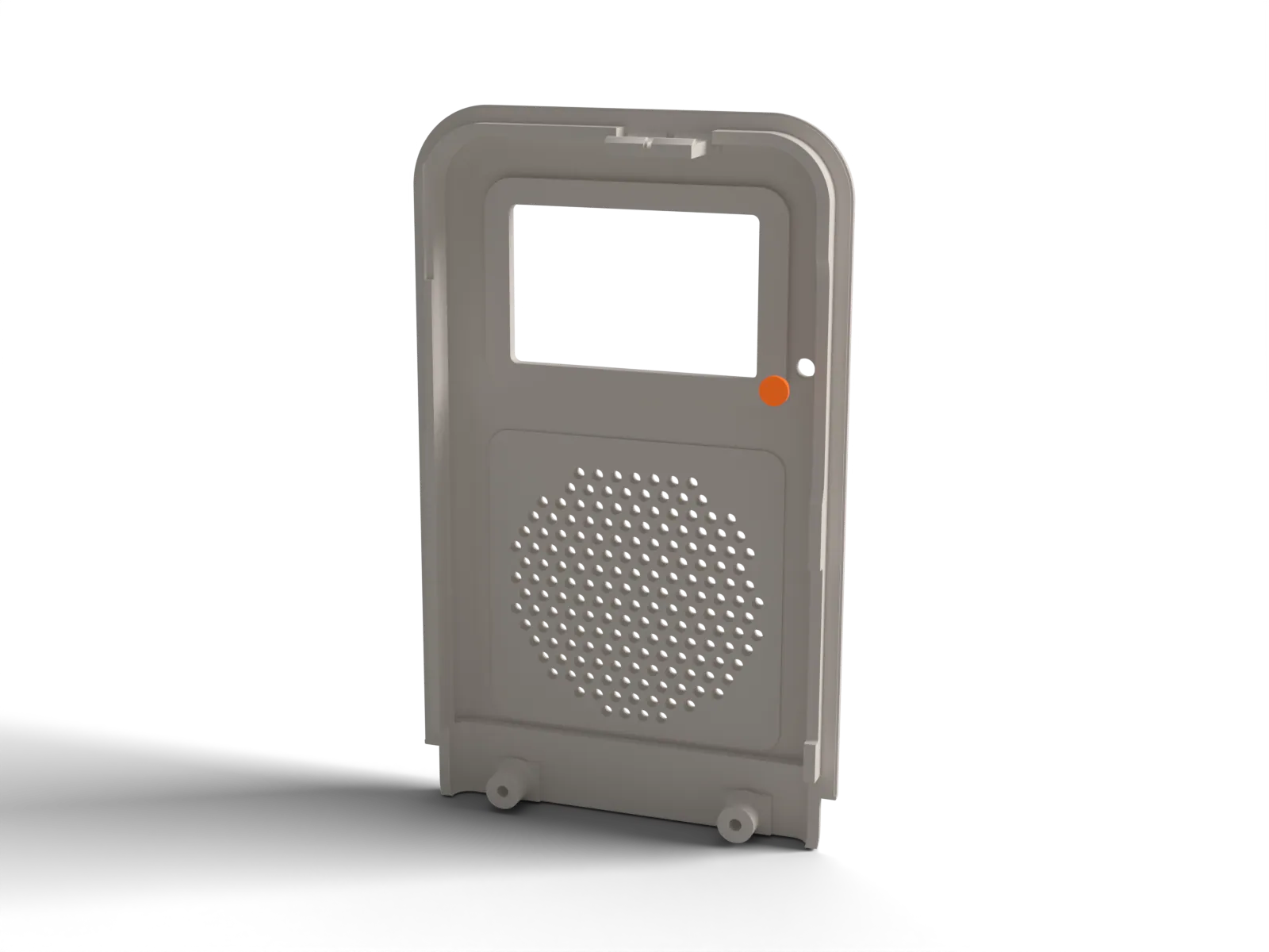
Push the clear plug through the small hole in the front wall of the lid, from inside, until its flange sits against the wall. The LED will later sit 2.7 mm behind the flange.
The tip is flush with the front face, not proud, and the flange lies flat.
- 02
Fit the glass, the bezel and the LCD mask
1 x glass pane, 1 x bezel, 1 x LCD mask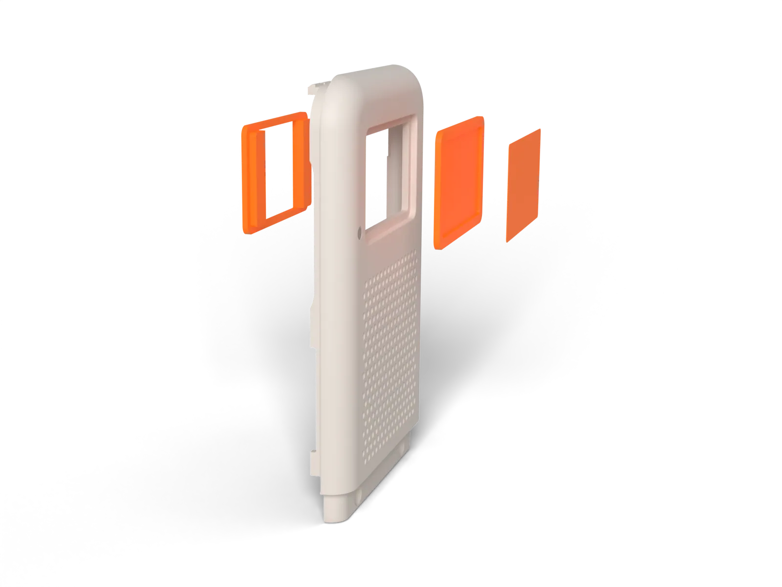
Lay the pane in the bezel: the bezel lip holds it. Put a thin bead of cyanoacrylate on the bezel's inner flange and seat the bezel in the window opening from the front. The screen is not glued to the pane. Then, from inside the lid, lay the black printed LCD mask on the back face of the window pad: its flange fills the pad recess and its two side blocks fill the window beside the 23.0 x 20.8 aperture. It is a dry fit; if it falls out while you handle the lid, put a pinhead of cyanoacrylate on two flange corners.
The bezel is square in the window, the pane sits behind its lip, and the mask lies flat with its aperture centred in the window.
- 03
Fit the SMA jack
1 x SMA bulkhead jack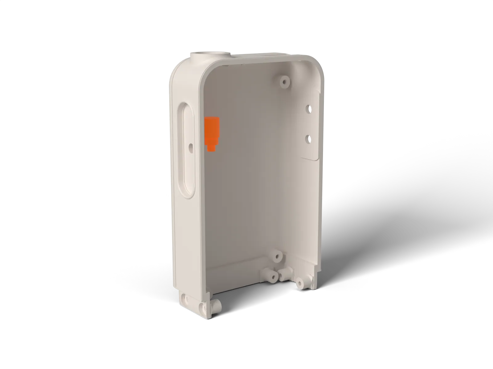
Pass the jack up from inside through the 6.5 mm panel hole in the top plate and fasten its nut on the outside, inside the collar. Tighten it by hand plus a quarter turn with an 8 mm spanner. No thread locker: the plate is only 1.6 mm thick.
The jack stands square in the plate and its nut has about 1.4 mm of room all round inside the collar.
- 04
Stick on the Wi-Fi antenna
Wi-Fi FPC antenna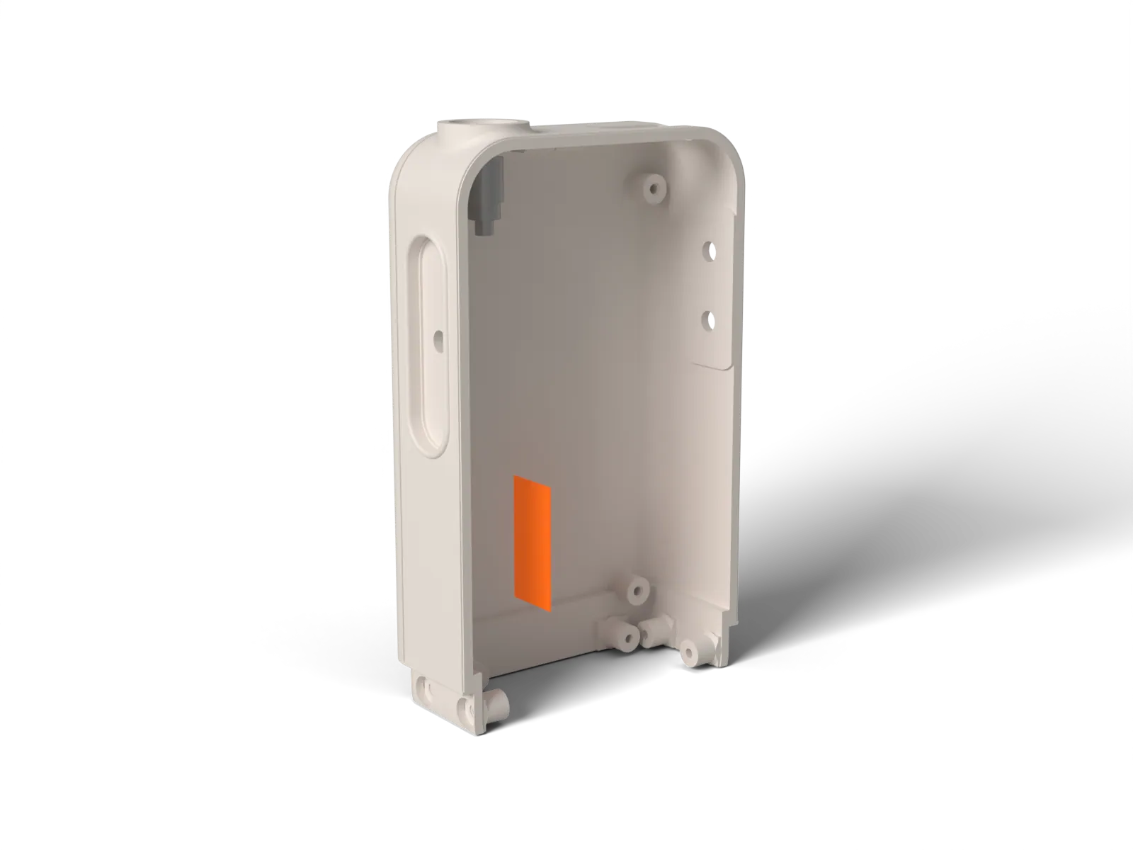
Stick the flat Wi-Fi antenna on the inside of the left wall of the tub, about 26 to 47 mm above the base, with its lead pointing down. Keep it clear of metal: no screws, no metallic paint.
The antenna lies flat with no air under it, and no screw is within 1 mm.
- 05
Fit the talk key and its ring
1 x talk key, 1 x key ring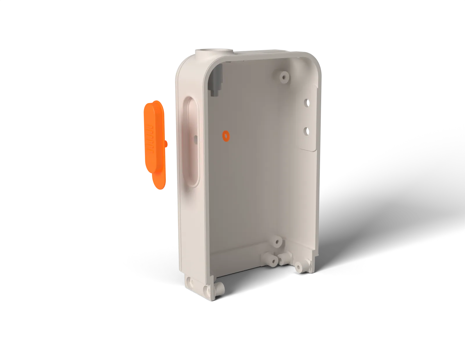
Work on the open tub, before the core goes in. Push the key's solid stem through the 3.6 mm hole at the back of its well, from outside. Then, from inside the tub, stretch the small flexible ring (1.9 mm bore, 4.4 mm outside, 0.5 mm thick) over the nub on the end of the stem until it sits in the groove behind the wall. The ring keeps the key in and lets it travel.
The ring sits in the groove, the key cannot be pulled out, and it moves freely in its well.
- 06
Fit the volume rockers and their rings
2 x rocker, 2 x key ring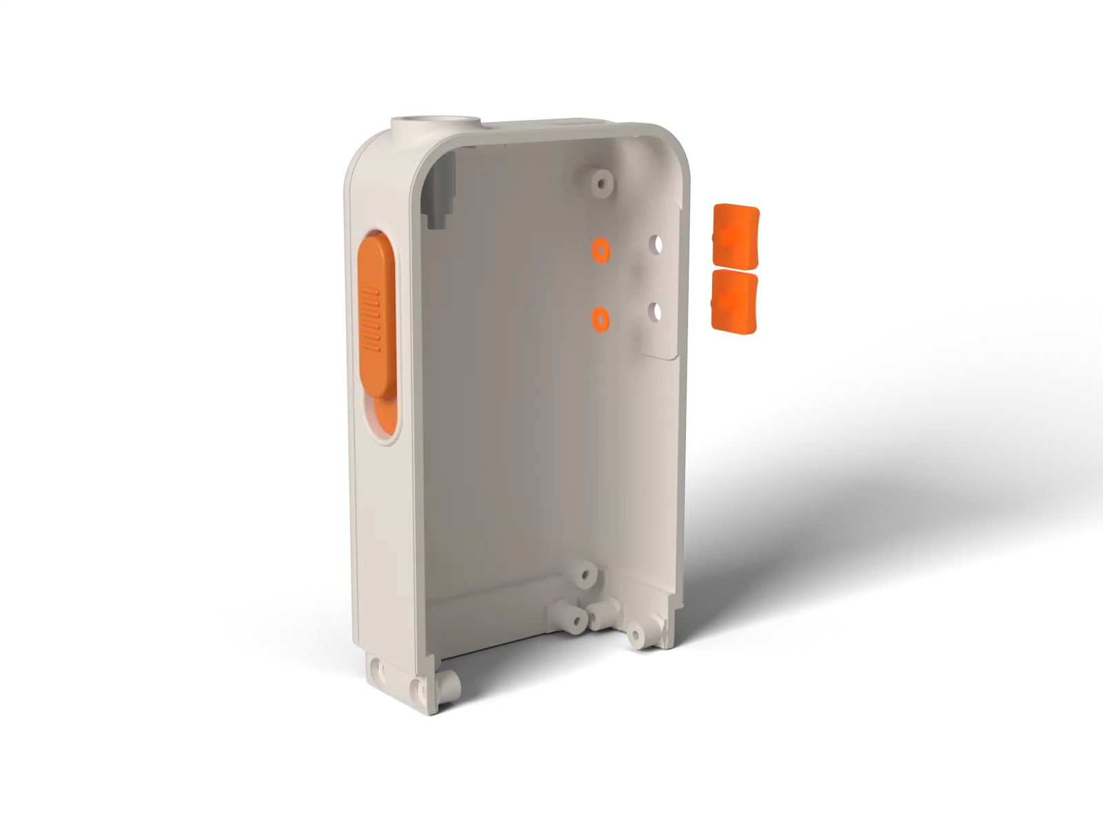
Fit each rocker and its ring in the same way, through the two holes in the right wall of the tub.
Both rings sit in their grooves and both rockers move freely.
- 07
Slide the battery into the cradle
LiPo battery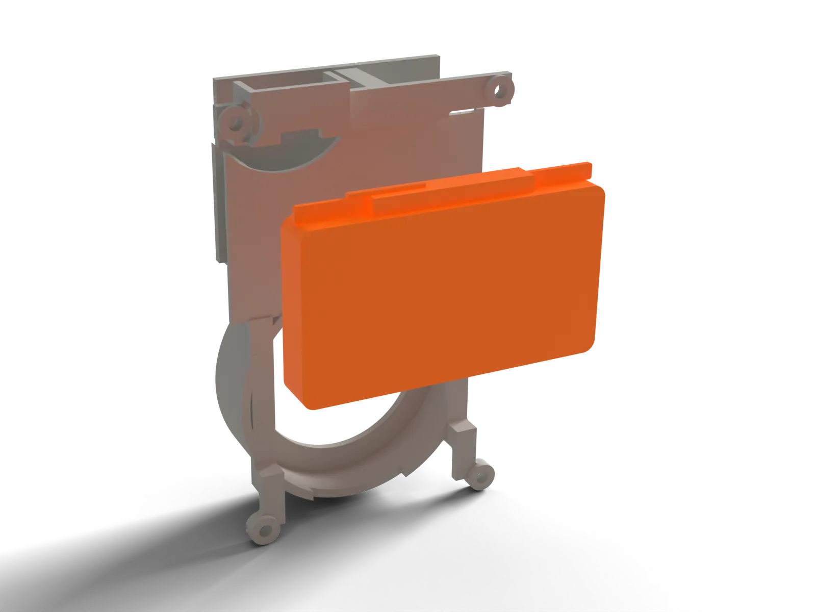
Cut the 3 pin plug off the CE06795 first (leave the leads long, strip and tin the red and black, insulate the third NTC lead). Then slide the 7 x 30 x 50 battery into its slot behind the deck from the back of the cradle. Keep its protection board and leads at the top edge. The slot leaves 0.75 mm for the cell to swell.
The battery lies flat behind the deck and nothing presses on the pouch.
- 08
Seat the XIAO stack
XIAO ESP32S3 + Wio-SX1262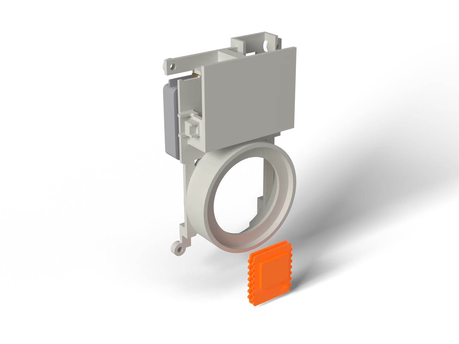
Stand the stack vertically in the base of the cradle with its USB-C pointing down and its component side facing the back. That puts the USB-C on the notch in the band base.
The USB-C is level with the base opening and the stack does not rock.
- 09
Hang the expander
Adafruit 5346 MCP23017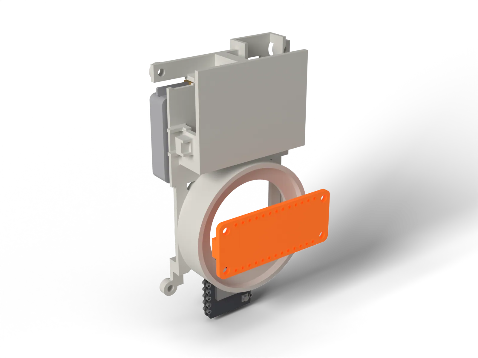
Press the expander flat onto the four cradle pins behind where the speaker will sit, with its two STEMMA QT sockets facing the XIAO.
All four corner holes are on pins and the board lies flat.
- 10
Fit the amplifier
MAX98357A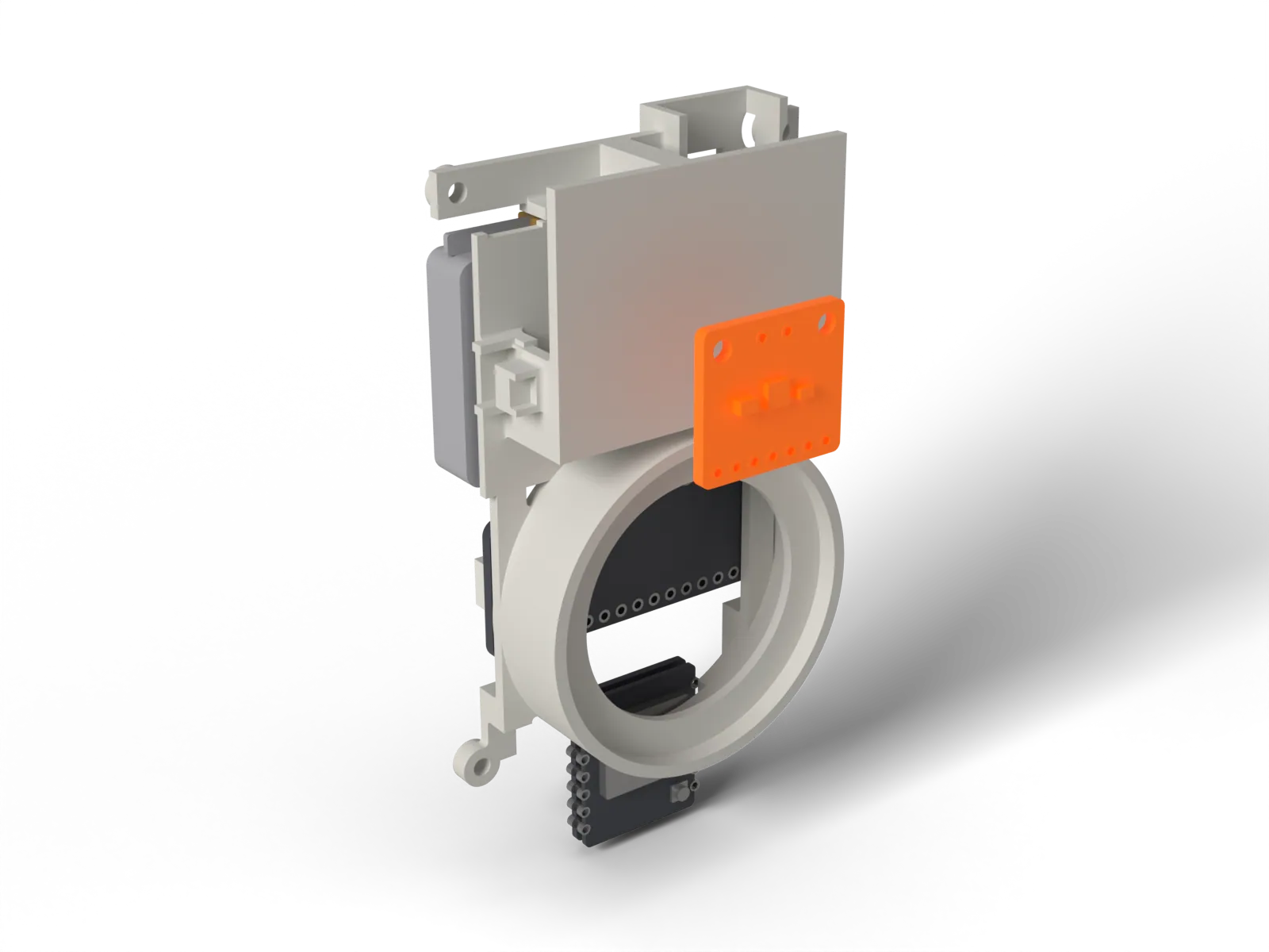
Fit the amplifier on the front of the deck, behind the screen tray. There is no boost board in this build.
The board lies flat and clears the wheel's pocket.
- 11
Fit the encoder, the switches and the LED
PEC11R encoder, 3 x side switch, LED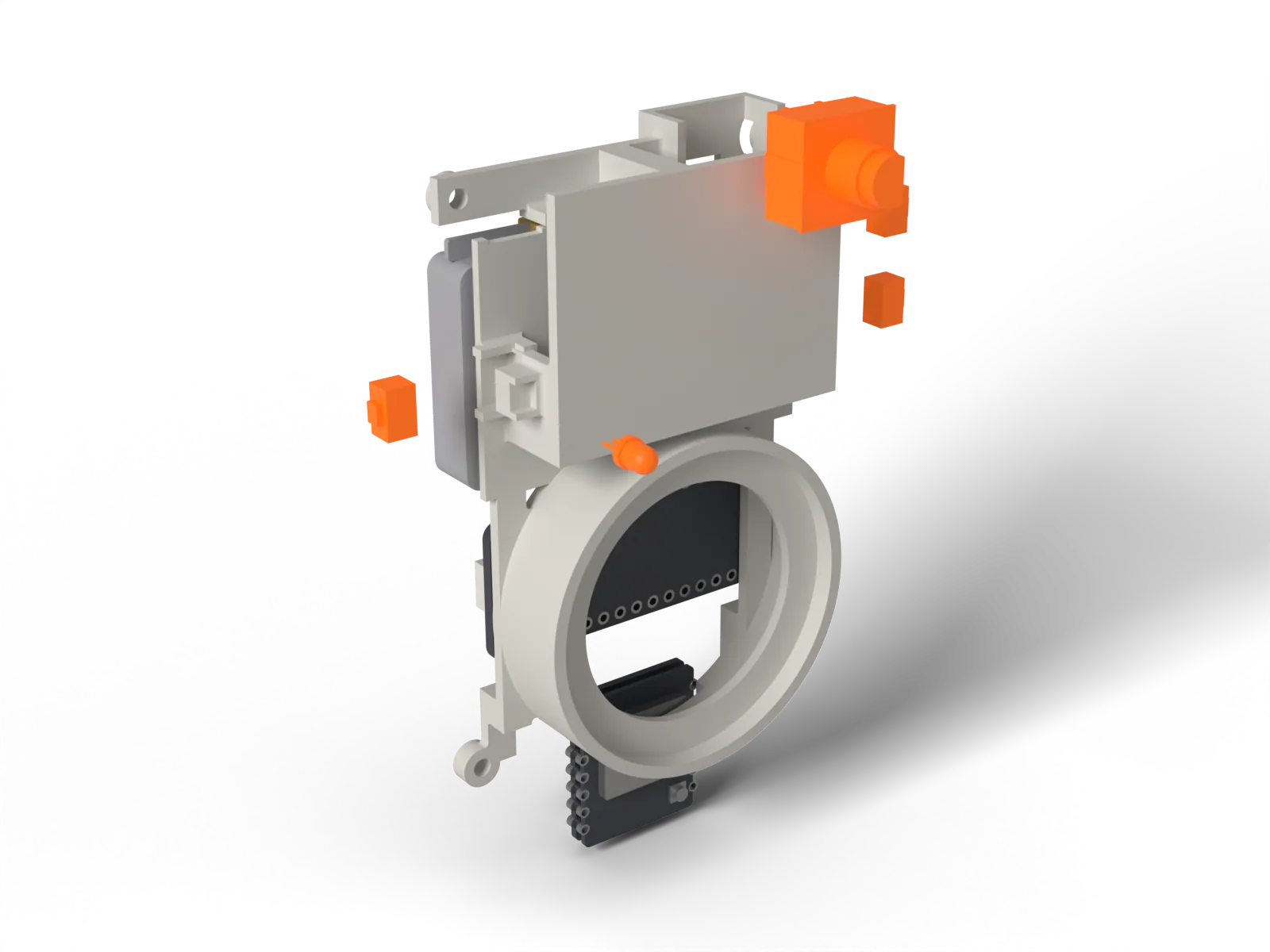
Drop the Bourns PEC11R encoder into its pocket with the shaft pointing forward. Its M7 bushing, 5.0 mm long, stands proud of the body. The talk-key switch goes in its pocket on the left and the two volume switches on the right, actuators facing outward, against their back stops. Clip the 3 mm LED, with its 330 ohm resistor, into its holder.
Each switch actuator faces the side wall and cannot move back. The encoder shaft stands clear of the pocket.
- 12
Fit the speaker and its foam seal
PUI 40 mm speaker, foam seal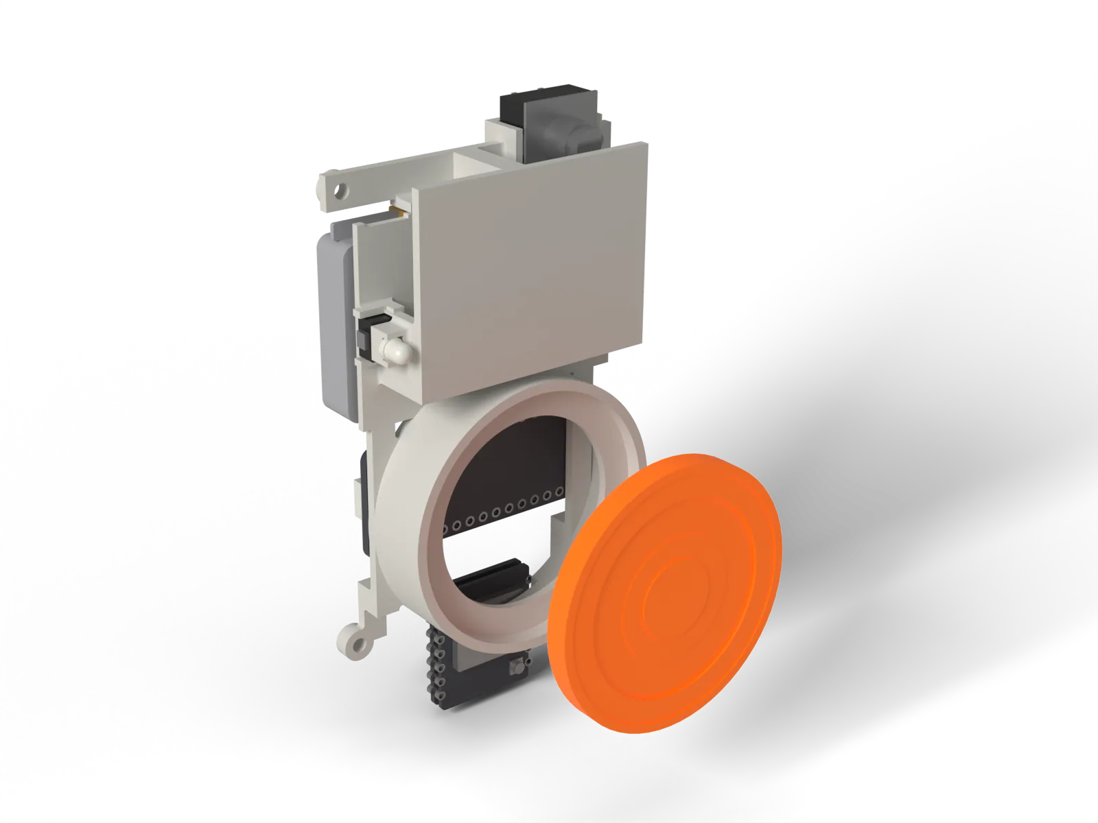
Press the PUI 40 mm speaker (5.0 mm thick) into its tube with a 1.0 mm closed-cell foam ring on the rim, leads out toward the amplifier. The lid will press the seal against the grille wall. The space behind the speaker is open to the case (about 22 cc); the front seal does the acoustic job.
The speaker is centred and the foam ring has no gap.
- 13
Fit the screen
Sharp LS013B7DH03, FPC adapter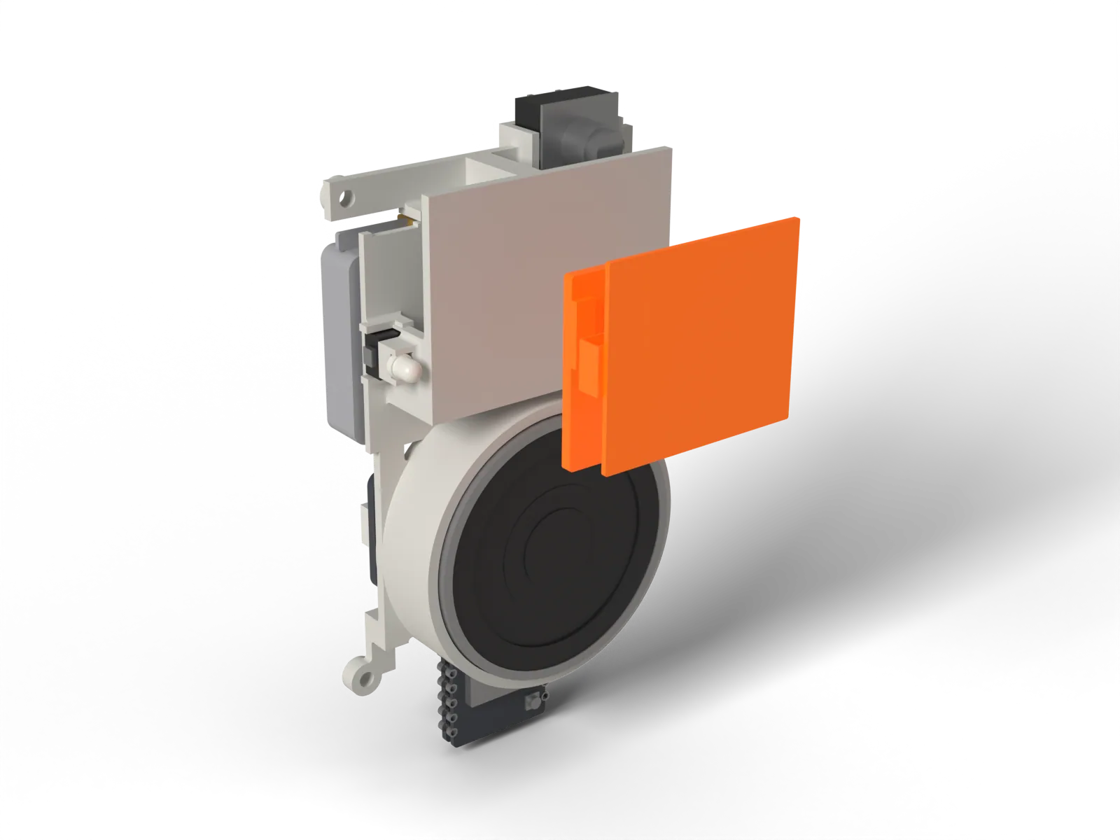
Lay the screen landscape on the tray with its flat cable on the left, on a 1.0 mm foam tape pad. It sits 0.1 mm behind the mask and is never clamped: Sharp asks for no stress on the glass. Then fold the flat cable once behind the panel (bend no tighter than 0.45 mm inner radius, never toward the polarizer) and close the flip-ZIF latch on the adapter. The fold and the adapter size are nominal, and the contact side must be checked on your adapter. The screen runs on 3.3 V from the XIAO.
The active area is centred on the window position and the cable is not kinked.
- 14
Slide the core into the tub
cradle with modules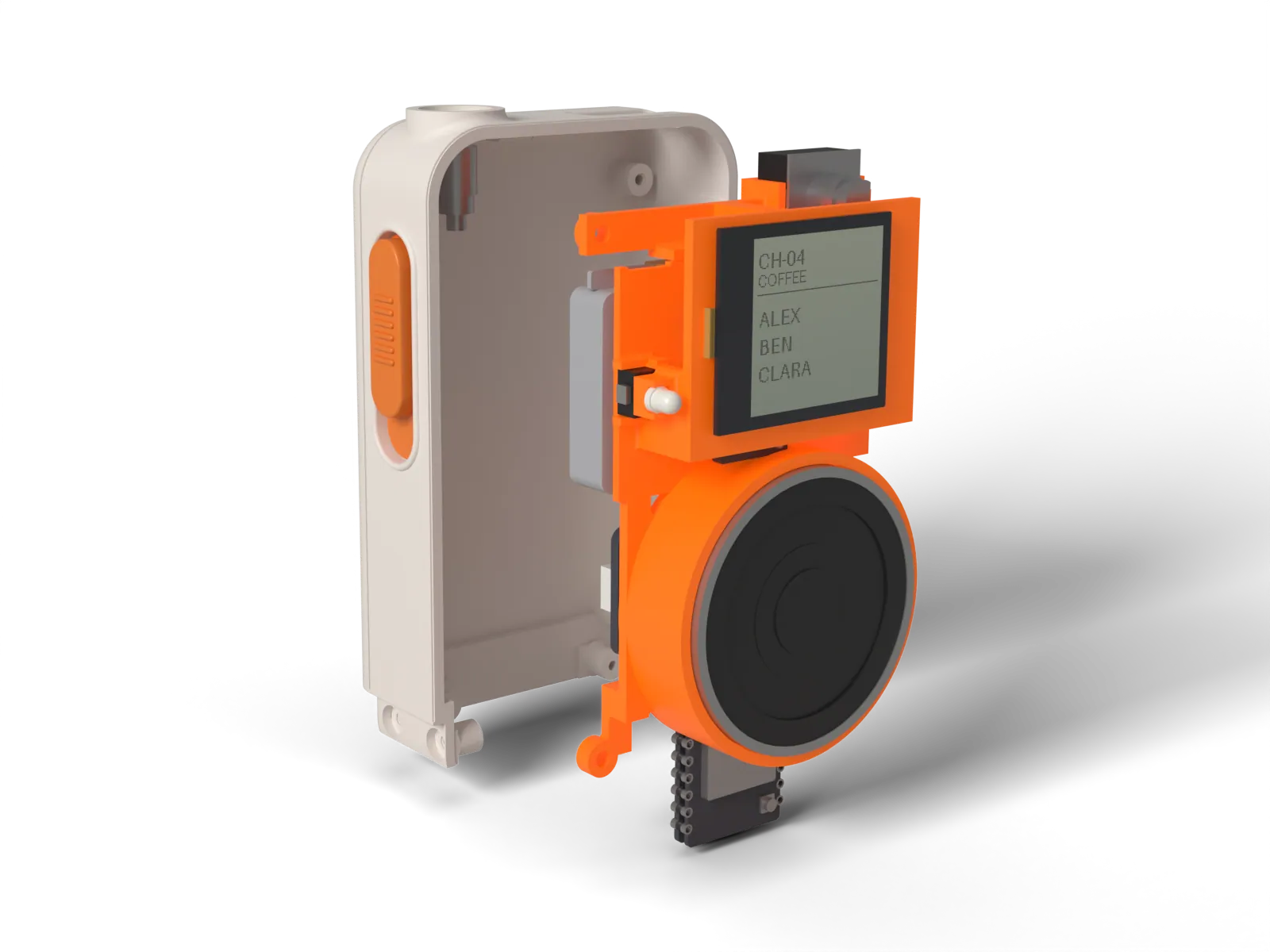
Connect the Wio-SX1262 u.FL pigtail to the SMA jack and the Wi-Fi antenna lead to the XIAO before the cradle seats. The three keys are already in the tub wall. Slide the cradle into the tub from the front, with its four lugs on the four bosses on the back wall, and check that each switch actuator meets the back of its key stem.
The lugs sit flat on the bosses and no wire is trapped.
- 15
Drive the four core screws
4 x M2 x 8 cap screw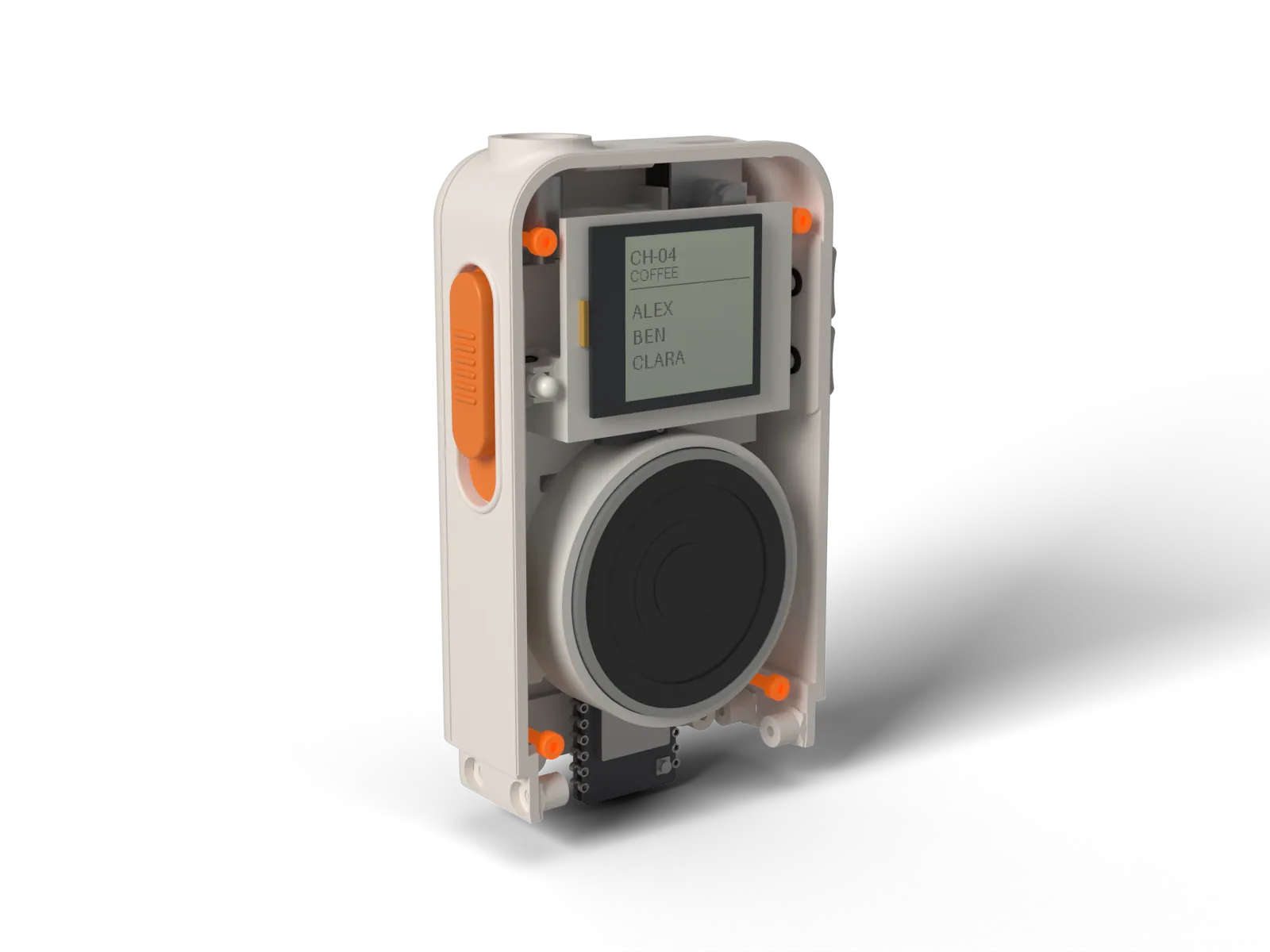
Drive one screw through each lug into its boss: two near the top and two low down, at 20 mm above the base. Each one forms its own thread straight into the 1.7 mm pilot. The lugs are 2.6 mm thick and the thread engagement is 5.4 mm.
The core does not rock and all four heads sit on the lugs.
- 16
Fit the wheel
1 x wheel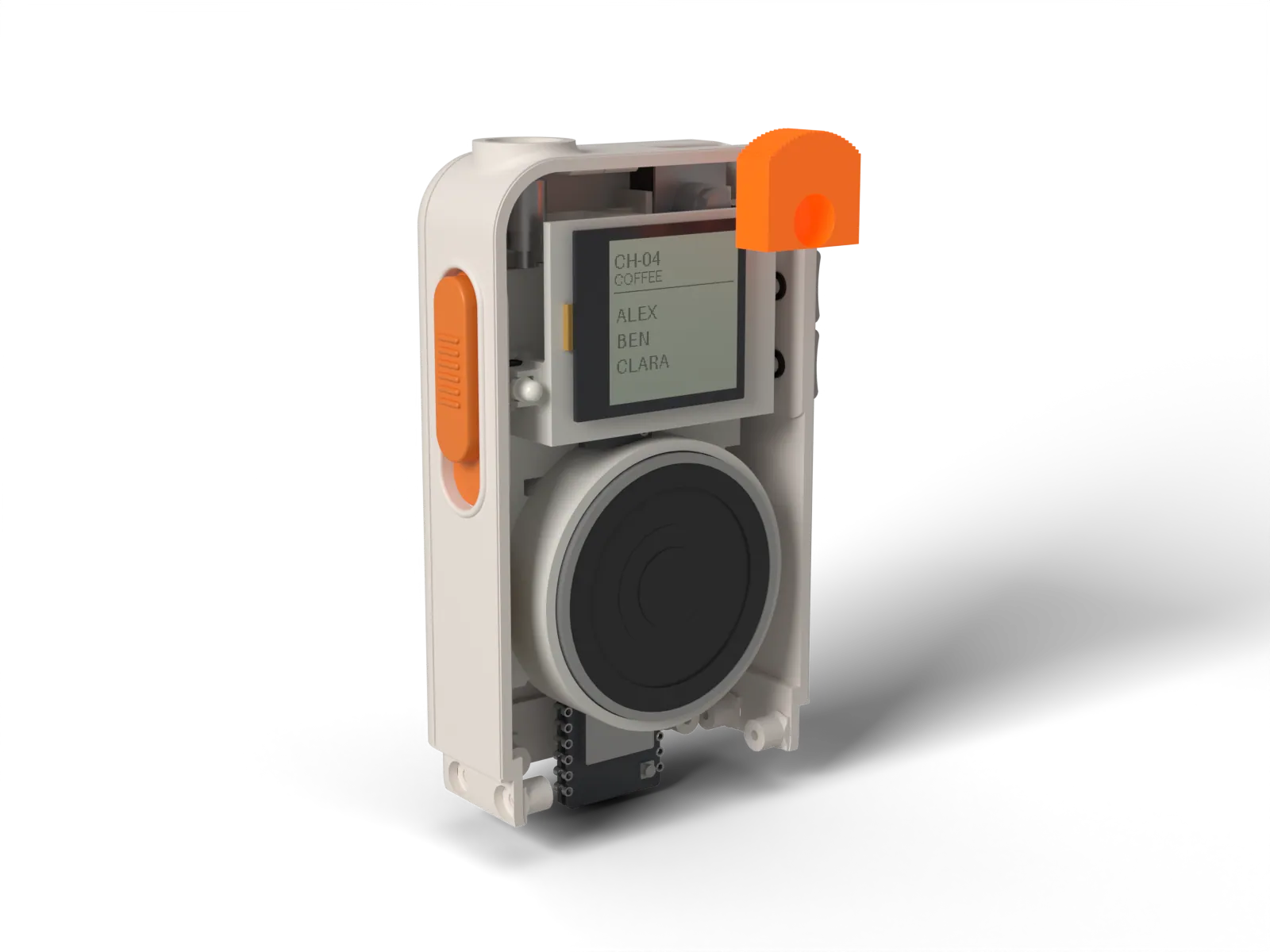
Push the bored wheel onto the encoder shaft through the slot in the top plate. The wheel takes the encoder bushing in its 7.5 x 5.3 relief and the bushing is its bearing; if the wheel does not seat, shorten the shaft. About 2.8 mm of its rim stands above the top.
The wheel turns freely, its sides clear the slot, and about 15 mm of it shows above the top.
- 17
Snap the lid on
1 x lid, with light, bezel and glass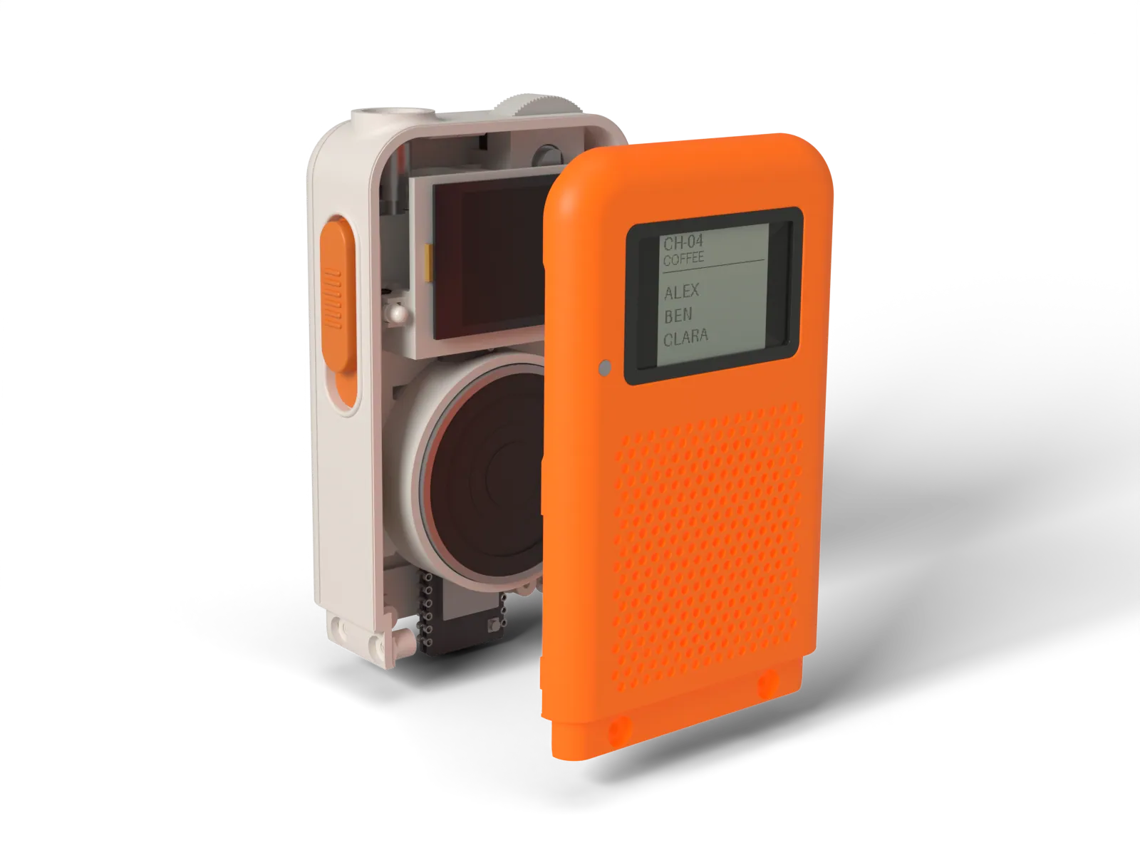
The band is still off. Hook the two barbs at the top into the catch pockets under the top plate, then press the lower edge in until the hooks click.
The lid closes with a click and the parting line is even from top to bottom.
- 18
Fit the microphone seat and the microphone
mic seat, INMP441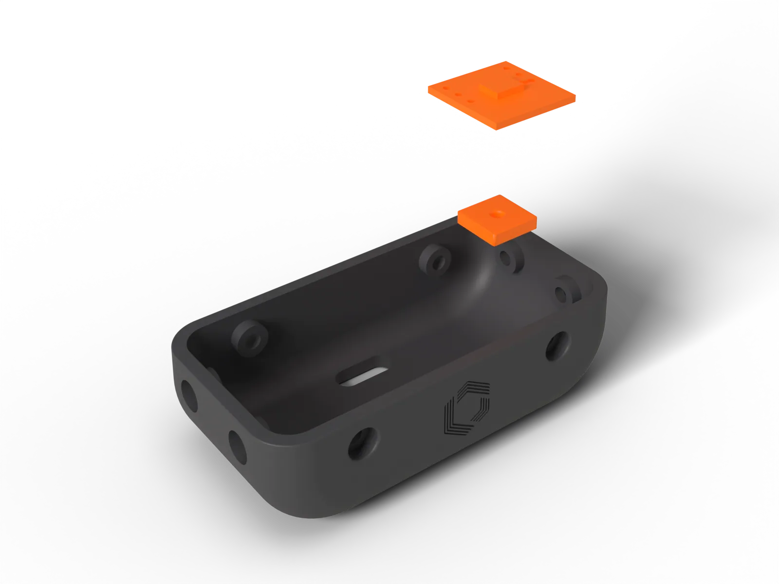
In the band, set the printed seat over the sound port in the floor, centred on it. Lay the microphone on the seat with its port down. Connect its leads to the harness first and leave a loop.
The mic port is centred on the casing port and the seat does not rock.
- 19
Slide the band on
1 x band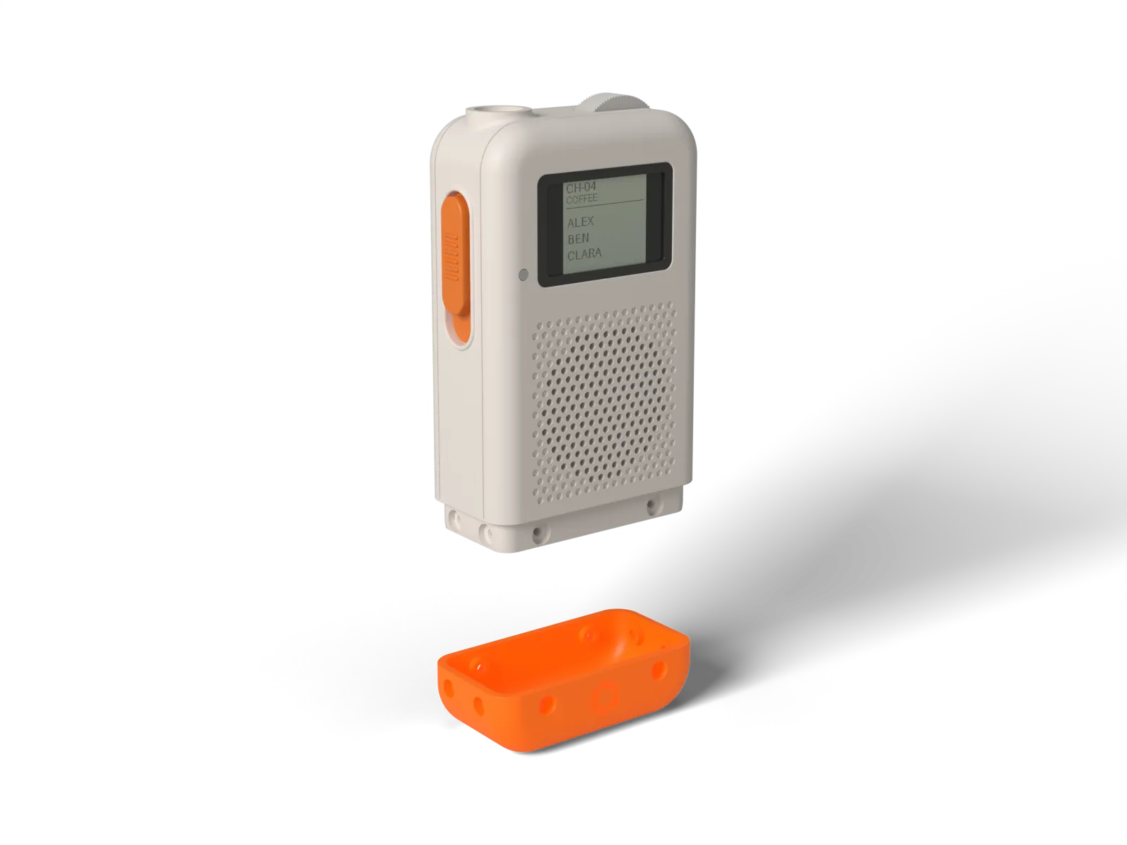
Slide the band up from below over the skirt that hangs from the shell rim, taking care not to trap the microphone leads.
The seam between shell and band closes evenly all round.
- 20
Drive the eight band screws
8 x M2 x 8 cap screw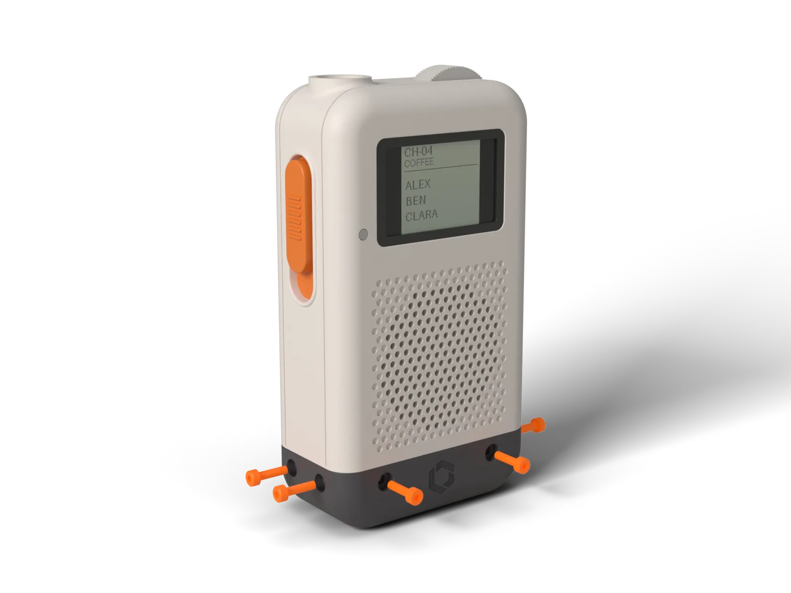
Drive two screws into the front face, two into the back and two into each side with the 1.5 mm hex key. Each goes through the band wall into a boss on the shell skirt. On the resin route the 1.7 mm pilot was tapped once with an M2 hand tap, so the thread lasts when you open the handset for service. On the PLA route the screw forms its own thread. Stop as soon as the head seats.
Each head sits 0.2 mm below the band face in its counterbore, none proud.
- 21
Fit the antenna and the boot
stubby antenna, 1 x boot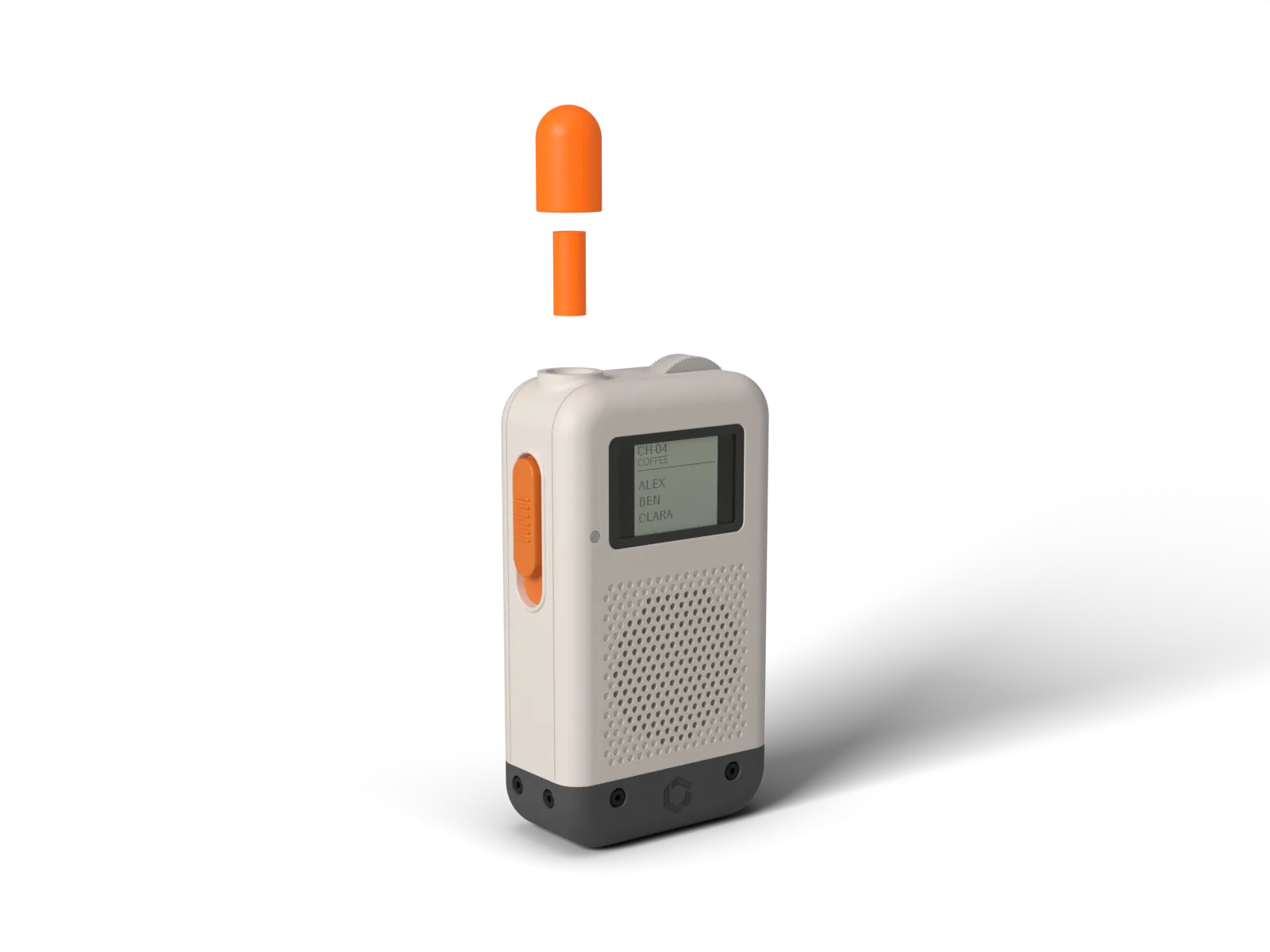
Screw the stubby antenna onto the jack by hand, then push the boot straight down over it until it stops. The flexible boot grips the stubby and stretches on, so press steadily. See section 10 for the fit.
A fine, even dark line of 0.15 mm shows between the boot and the shell collar all round.
- 22
The finished handset
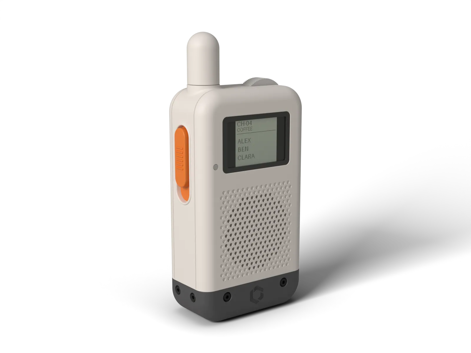
Press every key, turn the wheel, and look at the seams. The handset is mechanically complete. It will not talk until the firmware exists.
All three keys click and return (each travels about 0.4 mm), the wheel turns without rubbing, and the parting line and the boot seam are even.
Which screw goes where
| Fastener | Qty | Where | Resin route | PLA route | Driven | Step |
|---|---|---|---|---|---|---|
| M2 x 8 ISO 4762, black | 4 | through the four cradle lugs into the four bosses on the tub's back wall: two at the top (x +-23, 92 up) and two low (x +20 and -22.5, 20 up) | thread-forms straight into the 1.7 pilot (rarely undone) | thread-forms into the 1.7 pilot | from the front | 15 |
| M2 x 8 ISO 4762, black | 2 | front face of the band (x -16.35 and +16.35, 12.4 above the base) into the bosses on the lid skirt | pilot tapped once with an M2 hand tap | thread-forms into the 1.7 pilot | from the front | 20 |
| M2 x 8 ISO 4762, black | 2 | back face of the band, same positions, into the tub skirt bosses | pilot tapped once with an M2 hand tap | thread-forms into the 1.7 pilot | from the back | 20 |
| M2 x 8 ISO 4762, black | 4 | left and right faces of the band, 6.1 either side of the depth centre, into the tub skirt bosses | pilot tapped once with an M2 hand tap | thread-forms into the 1.7 pilot | from the side | 20 |
The screw is the standard black M2 x 8 socket cap (head 3.8 x 2.0, 1.5 mm hex socket). All twelve are the same, ISO 4762, black, from an ordinary kit (A$0 if you have one). The band counterbores are 4.4 x 2.2, so the head ends 0.2 mm under the face with a 0.4 mm rolled lip round it. Every pilot is 1.7 mm with a 2.2 x 0.3 entry counterbore: band bosses give 5.25 mm of thread, core bosses 5.4 mm. On the resin route the eight band screws are opened for service, so their pilots are tapped once with an M2 hand tap (Tough 74 v2 takes tapping well) and the thread lasts. The four core screws are rarely undone and thread-form straight into the pilots. On the PLA route all twelve thread-form into the pilots. Drive gently and stop when the head seats. If a pilot loosens after a few cycles, a drop of cyanoacrylate in it restores it. The kit has no M2 x 6, which is why the core bosses are tall and the cradle lugs 2.6 mm thick. Washers are not used.
Fixings that are not screws
tape, foam, glue, rings| Fixing | Qty | Where | Step | Note |
|---|---|---|---|---|
| 1.0 mm foam tape pad | 1 | between the screen and the cradle tray | 13 | the screen sits 0.1 mm behind the mask, never clamped |
| 1.0 mm closed-cell foam ring | 1 | on the speaker rim, pressed by the lid against the grille wall | 12 | the front seal does the acoustic job |
| Cyanoacrylate, thin bead | 1 | bezel inner flange to the window opening (and, only if the mask falls out, a pinhead on two mask flange corners) | 02 | the only glue in the build |
| 1.0 mm foam tape under the mic seat | 1 | between the mic seat and the band floor | 18 | keeps the microphone port sealed to the casing port |
| F69 or TPU key ring | 3 | over the nub of the talk key and of each rocker, inside the tub wall | 05, 06 | ring ID 1.9, OD 4.4, 0.5 thick |
| Foam or tape for the battery | 0 | none: the battery lies in its bay behind the deck | 07 | keep 0.75 mm of swell room; no tape on the pouch |
There are no captive nuts and no heat-set inserts in this build. An M2 nut pocket needs a 7.4 mm boss and an M2 insert a 6.4 mm boss. The room at the bosses is 5.1 mm (side bosses, held by the lid to tub joint), about 6.2 mm (right bosses, mic board) and 5.6 to 6.0 mm (upper core bosses, encoder and battery). The c2 encoder is 12.5 deep (Bourns PEC11R): its top back corner is 0.55 mm from the tub top wall, an exception that needs no change to the screws.
Antenna boot fit
The boot is a separate printed sleeve that stretches over the stubby antenna and leaves a deliberate dark line of 0.15 mm between itself and a collar moulded into the shell. The line is a feature: it makes the handset look machined.
| Item | Value |
|---|---|
| Collar on the shell | 14.3 mm dia, crisp top edge (0.1 mm break), bore 5.4 mm, wall 1.75 mm |
| Boot | 14.0 mm dia, 24.2 mm above the top plate, bottom outer edge rounded 0.3 mm. Resin route: F69, flexible. PLA route: TPU 95A |
| Seam | 0.15 mm, set by the antenna top stopping against the socket end |
| Socket | 6.0 mm deep, over the stubby's 3.5 mm radius body. Resin route: 3.1 mm radius in F69 (0.4 mm grip, stretches on). PLA route: 3.3 mm radius in TPU |
| Room round the plug nut | bore 5.4 mm radius, 1.4 mm clear; antenna top 4.9 mm under the dome |
| Stubby antenna | 17.7 mm high, straight SMA, 915 MHz |
- Screw the stubby antenna onto the jack by hand.
- Push the boot straight down over it until it stops. It stretches on.
- Look at the seam: it should be an even dark line all round.
The F69 boot cannot be prototyped in a rigid resin. The prototype boot (c2_resin_proto_antenna_boot, ABS-Like 3.0, 0.1 mm press fit) is for look and fit only. If a boot is too tight to push on or falls off, use the boot_grip coupons to find the next size. If the line is too thin to see, the gap can go to 0.2 mm in the CAD; that is a casing change, not a fix to make with a file. A longer quarter-wave antenna needs a taller boot, which is not drawn.
Troubleshooting
| Symptom | Likely cause | Fix |
|---|---|---|
| Lid and tub | ||
| The lid will not close | a module or a wire stands proud of the cradle | open the lid, reseat the cradle on its four bosses and check the wires |
| The hooks do not click | a hook is bent or the catch pocket is tight | check the barb is 0.6 mm with 0.15 mm clearance; ease the pocket by 0.1 mm; check the lid is Tenacious (resin route) |
| A hook cracked or snapped | the lid is in a notch-sensitive resin, or a hook was bent too often | print the lid in Tenacious, not Tough 74 v2. The hook strain is 1.95 percent, well under Tenacious's 70 percent elongation. PLA route: reprint the lid and bend the hooks as few times as you can |
| The parting line is uneven, the top rocks | only two hooks hold the top | a third hook beside the rocker side is possible; report which corner lifts |
| Screws and band | ||
| A screw spins in its boss | the pilot was stripped | a drop of cyanoacrylate in the pilot; do not overtighten |
| A screw head sits proud | the counterbore is shallow after printing | ream the counterbore (4.4 x 2.2); one print should fit one kit screw |
| The band will not slide on | elephant foot on the skirt | sand the first layer edge |
| Keys, wheel and light | ||
| The key will not go through its hole | the stem hole is small | the stem is 3.0 mm in a 3.6 mm hole (0.3 mm per side); check the hole against the stem_hole coupon |
| A key falls out, or its ring slips | the ring is off the groove, or the ring or the groove is the wrong size | seat the ring in the groove from inside the tub; if it still slips, print the next coupon size of ring or groove |
| A key sticks | no clearance behind the well, or burrs | sand the stem and the well; the key must drop 0.4 mm |
| The wheel rubs | slot narrow | sand the slot, 7.8 mm deep and as wide as the chord |
| The status light shows dark | the plug is not clear or not seated | reprint in Tenacious Clear (PLA route: clear PETG); press the flange against the wall |
| Core | ||
| A module does not clear its boss or wall | the bought part is bigger than its CAD size | measure it, tell the CAD owner; do not file the casing |
| The battery does not fit | a bigger pack was bought (the bay takes 7 x 30 x 50 plus 0.75 mm swell room) | use the Core Electronics CE06795 or the fallback in the parts list; the 51 x 34 x 6 pack does not fit |
| The cradle does not seat on the bosses | supports left in the lug seats or elephant foot | clean the lug seats flat; the lug is 2.6 mm thick |
| The wheel will not go on the shaft, or rubs | the encoder bushing is longer than the 5.0 mm PEC11R one (the Alps fallback is 7.0), or the D bore is tight | the wheel relief is 7.5 wide x 5.3 deep: deepen it for a longer bushing or cut the shaft to length; check the bore against the wheel_bore coupons |
| The screen cable does not reach the adapter | the tail fold or adapter is not the NOMINAL size | measure both; tell the CAD owner |
| The boot is loose or tight | socket radius | see section 10 |
| A part has bent or gone soft | it was left in heat | resin parts soften around 55 to 60 C: keep the walkie out of hot cars and off dashboards |
Licence and credits
| What | Licence |
|---|---|
| Hardware: the casing, the interface files, the electrical reference | CERN-OHL-W-2.0 (as the PN-84 family; to be confirmed before release) |
| Firmware, when it exists | Apache-2.0 (as the PN-84 family; to be confirmed) |
| Documentation: this manual and its images | CC BY-SA 4.0 (to be confirmed) |
| Fonts embedded in this page: Inter, IBM Plex Mono | SIL Open Font License 1.1 |
Shortwave is a name used by Reactive Pixels and is not licensed by the above. The parts named in the bill of materials belong to their makers (Seeed Studio, Sharp, TE Connectivity, Adafruit, Same Sky and others) and are bought, not redistributed.
© 2026 Rod Leviton, RPXL / Reactive Pixels. The Shortwave page and the rest of the range: Pigeon. More from the studio at reactivepixels.com.